Posted on 10/1/2009
Source: Optimizing the Ares V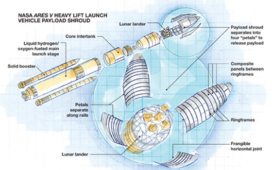
Sizing software allows rapid analysis of candidate composite architecture for highly loaded and weight-sensitive launch vehicle component.
Design Results
- Increasing confidence in the technology has led to consideration for the first time of composites for manned space flight, including the Ares V launch vehicle.
- Optimization software permits designers to choose from thousands of material types to build and test virtual laminates as they seek the best design.
- Stiffened, uncored panels could present the best option because their structural performance can be highly tailored for the lightest weight.
After 40 years, the U.S. National Aeronautics and Space Admin. (NASA) has again targeted the Moon — and more distant destinations — for exploration. Its Constellation mission, authorized in 2005, will replace the aging Space Shuttle program, and could transport astronauts as far as Mars, depending on funding. Notably, the program marks the first time that composites have been considered for manned mission hardware.
NASA already has designed and built a full-scale Composite Crew Module (CCM) in parallel with the mostly metallic Orion crew exploration capsule that will fly as part of Constellation (see “Learn More,” at right). In addition, the payload shroud, interstage and intertank structures of the Ares V heavy-lift launch vehicle, also part of the Constellation concept, are being conceptually designed in composites, under the NASA-funded Advanced Composites Technology (ACT) project’s $100 million (USD) research budget, says Craig Collier of Collier Research Corp. (Hampton, Va.), a former NASA Langley research engineer.
The Ares V is a three-stage rocket: Like the Space Shuttle, it will use a pair of solid-fuel first-stage rocket boosters that will burn simultaneously with the liquid-fuel second (core) stage. The upper stage, dubbed the Earth Departure Stage (EDS), will be powered by a liquid hydrogen/liquid oxygen rocket engine. At 116m/380 ft long and 10m/33 ft in diameter, Ares V will be the world’s largest launch vehicle. It also will be the most powerful, able to lift 188,000 kg/415,000 lb into low earth orbit, or 71,000 kg/157,000 lb to the Moon.
Design of the Ares V components has been facilitated by Collier Research, using its HyperSizer software. First developed in the early 1990s at NASA’s Langley Research Center (Hampton, Va.), HyperSizer does not perform finite element analysis (FEA) and is not a computer-aided design (CAD) program, stresses Collier. “It’s a tool for composite designers that provides automated structural analysis, material selection and design optimization.” The software is designed to help the user select the best composite materials for an application and determine margins of safety, for the lightest possible structure. Collier’s company is currently part of a NASA team that aims to determine the optimum structural concepts for the largest composite component on Ares V, the 33-ft/10m-diameter and nearly 72-ft/22m-long payload shroud that will surround the lunar landing hardware.
Optimizing composite laminates for strength
The shroud is envisioned as a four-petal, ogive-shaped enclosure that, at the appointed time in flight, will explosively separate along a frangible horizontal joint above the interstage and along four “rails,” jettisoning the four petal segments to release the lunar lander. For this component, Collier and the NASA team first developed a finite element (FE) model, using Nastran and Abaqus FEA software from SIMULIA (Providence, R.I.); the model mesh is shown at upper right, with dark lines representing the ring frames and the four petal-separation rails. The external dynamic flight pressures were resolved through the FE model mesh to determine the internal “design-to” loads for the HyperSizer software, explains Collier, noting that the software also works without FEA, as long as design-to loads are known.
The FEA calculated the stress resultants or shell element unit forces in both x and y directions, and showed that the highest loads were in the axial (compressive) direction on the order of –454 kg/–1,000 lb per inch of vehicle circumference, as expected. But, says Collier, “the higher flight pressures in the nose region caused relatively high internal hoop compression [Ny] loads, which are particularly challenging for sizing stiffened panels.” In-plane shear loads (Nxy) for the shroud were not significant, he adds.
With the design-to loads established, the team conceived an initial design of composite panels between each ringframe and spanning the distance between the four petal separation rails (the ringframes and rails themselves are currently envisioned as composite profiles, although the final material selection has not yet been made). Panel candidates included cored sandwich panels and stiffened panels, the latter featuring uncored, monolithic laminates with hat stiffeners bonded or comolded with the panel to prevent buckling. HyperSizer provided a means to quickly establish the best — i.e., the lightest — panel concept.
The software’s Material Manager module allowed the designers to select from an integrated database of specific composite materials — these include some of the materials found in the Composites Material Handbook (CMH-17) — but also permitted them to import specific, user-defined materials and custom layups. The designers built composite laminates, systematically stacking different material forms or types simply by using Windows’ cut, paste and copy functions for quick ply insertions and practical layup arrangements. HyperSizer’s analytical modules (HyperSizer Basic and Pro) subjected the material layups to detailed stress analyses, using hundreds of failure modes.
Collier points out that the team considered ply-based and laminate-based approaches for optimization. In a nutshell, ply-based analysis determines the strength of the total laminate by computing the stress/strain in each ply. To do so, each individual ply’s material angle is a critical input into the calculation — typically, engineers assume that the total laminate fails whenever the first ply fails. On the other hand, laminate analyses do not try to establish the stress/strain in each individual ply, but instead calculate the effective stress/strain of the total laminate and compare it to an empirically based allowable curve. “The NASA team chose the ply-based approach to failure analysis, with the option of switching to a laminate-based approach in the next phase — the software allows either approach,” he adds.
Sandwich vs. stiffened panel
The designers selected various panel concepts from the materials database, using the cut-and-paste features. These included a two-stack, honeycomb-cored sandwich, with a variety of facesheet materials and core thicknesses, as well as open-section and closed-section stiffeners, with varying fiber architecture in the skin vs. the stiffener. Then, for each panel concept, the software rapidly analyzed more than 100 composites-specific failure modes, including flat-wise tension, facesheet wrinkling, intracell dimpling, core shear and crimping for sandwich concepts, and local buckling, crippling, and panel buckling for stiffened panels. For each panel design, the software calculated whether that particular combination of materials and layup could bear the known loads with an acceptable margin of safety, by automatically graphing the failure envelopes and the stress/strain profiles, using standard quadratic failure criteria, such as Tsai-Wu.
When the failure results were examined, Collier notes, it became obvious that a design approach in which “large acreage” areas of the shroud were assumed to require identical layups resulted in overdesign, as indicated by the dark purple color in the figure at right. Says Collier, “These areas represent margins of safety well above 1.0, meaning the entire large area must be able to withstand the load of any small, localized stressed area.” In the figure at far right, he explains, ”the lighter colors mean panels have been optimized by taking material out, with ply drops, and with customized materials, for a lighter overall design.”
According to Collier, the optimization process yielded lighter results with stiffened panels because their greater complexity offers more opportunity to save weight, due to the additional sizing variables. For example, the stiffeners can have primarily 0° plies while the skin can be dominated by 45° and 90° fibers. Further, detailed ply-level tailoring is possible for greater weight savings than with a sandwich design: “While sandwich panels do perform well in biaxial compression loading, the core material and associated bonding adhesive weight is parasitic — that is, it doesn’t directly contribute to the panel’s strength, which is a disadvantage.” In contrast, Collier points out, all of the material in a stiffened panel carries load, but laminate thickness and material layups must be precisely designed to prevent compressive load instability in the individual panel segments between the stiffeners.
Optimizing for manufacturability
When the panels were optimized for strength and positive margins of safety were confirmed for all potential failure modes, HyperSizer was used to optimize the entire structure for “ply compatibility.” That is, the software determined not only the best design but the most practical layup as well. “This new capability, which we added within the last year, proves manufacturability by determining the most efficient layup sequence, and can help develop programs for automated processes as well,” notes Collier.
The software generates a series of global sublaminate stacks (GSS) within which all plies are continuous throughout the entire panel or part — these are placed on the tool side (either OML or IML). If ply drop-offs or adds are required, they are placed near the laminate midplane, between GSS (see the bottom figure, at right). This minimizes drop-offs on the tool, making it much easier to manufacture the part.
The software also prioritizes ply drop-off order, avoiding “stair step” drops that can greatly diminish laminate performance. “Well over a million candidate layup arrangements across each panel surface were evaluated so that the lightest design was also the most manufacturable,” Collier reports.
Finally, HyperSizer’s PC-compatibility enabled multiple team members to run the program on different computers, all with access to the same database. Each engineer’s results were documented and maintained, and complete stress reports were available for later airworthiness documentation.
NASA recently conducted a rigorous “figure of merit” (FOM) process to score the candidate shroud concepts, with weight savings as the most important metric. Although details were not released by NASA, Collier reveals that if the Ares V shroud is ultimately designed as stiffened panels, the skins will have to be thicker than expected for an axially loaded structure: It will require a high percentage of 90° plies if it is to react the tension hoop load caused by internal pressurization yet also withstand crush pressure. The axial loading during launch requires special attention to prevent panel buckling — the thick skins and stiffener webs with +/-45° plies would counteract such buckling forces, he says.
As the program progresses, NASA will continue to evaluate candidate designs against very rigorous metrics that include repairability, damage tolerance, cost and technology readiness, as well as weight. Only time will reveal the final shroud materials and design. But the fact that composites are onboard at all indicates that the technology is maturing and might yet earn its way into the program: “This composites optimization process for Ares V,” concludes Collier, “has shown potential to reduce the weight of traditionally accepted launch vehicle designs by 30 percent.”