Analysis Workflow
Aerospace stress analysis methods simultaneously executed to thousands of load cases. Immediate interactive feedback to the engineer on the FEM: critical failure modes, load cases, and margins of safety.
Feature Pages

Introduction
Read how our software was used to design and analyze this Bell V280 tilt rotor helicopter fuselage in 22 months. Designing Bell Helicopter’s Next Gen Tiltrotor Fuselage
“To meet the aggressive V-280 schedule, HyperSizer was employed in a ‘design-by-analysis’ approach that successfully sized and analyzed the fuselage structure… The software also provided the engineers with automated stress-report generation that enabled them to review and vet all relevant data in order to prove-out the structural soundness of the fuselage.”
HyperX’s stress analysis framework process executes all failure analyses and speeds up the total solution time dramatically, while enforcing that all individual analysis methods share the same one source of truth data such as material allowables.
Steps
- Use a HyperX database template that contains your standardized materials and analysis, design, and load properties
- Import the FEM (See FEM workflow) and
- Automatically convert FEM properties into panel and beam zones
- Automatically preserve FEM data such as PCOMP/PCOMPG and define laminates and sandwich panels in HyperX
- Assign Analysis and Load properties to the zones (drag and drop onto the FEM)
- Analyze and report margins of safety, critical failure modes and load cases
These steps, from FEM import to producing aerospace analysis results for all load cases, can be performed in a matter of minutes – even for large models
Analysis Property
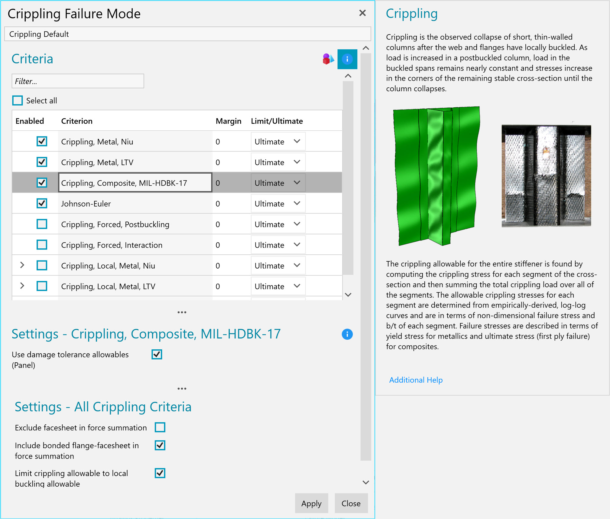
Set the types of analyses to execute. Analysis criteria can be individually toggled on/off, providing flexibility and visibility of their assignment on the FEM.

Failure criteria are central to analysis and design. The selected criteria are critical to ensure the structure is safe under the required loading. HyperX provides analysis properties to manage failure criteria and settings, offering transparency to the user.
Conveniently categorize and maintain these analysis properties in the property tree, along with design and load properties. Dragging and dropping analysis properties onto the FEM zones gives the user flexibility and visibility regarding the locations of specific analyses performed on the FEM.
Analysis properties are organized using failure mode categories. Failure modes themselves allow users to select criteria and adjust related settings. The HyperX forms provide descriptions for each failure mode category and their individual criteria, with quick links to the methods documentation.
Similar to design and load properties, analysis properties can be included in database templates. This allows multiple users in a group to use consistent criteria and analysis settings while working independently, improving overall productivity.
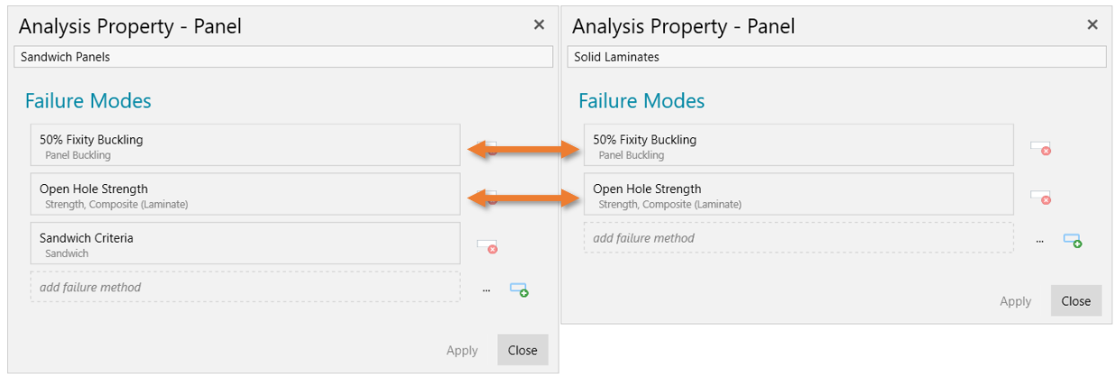
Failure modes can be shared between analysis properties. This allows commonality in criteria and settings even across panel concepts. By referencing the same failure mode, the user has transparency to a consistent strength approach application to a FEM.

Even though a stiffened panel has criteria – like crippling – which are unique to that panel concept (left), the active laminate strength methods can be the same for the stiffened panel as for a solid laminate panel (right).
Users can develop their own analysis failure methods and criteria for direct integration into HyperX. Custom methods written as analysis plugins can be selected alongside native methods and be used for both sizing and final analysis use-cases.
Directly related to the analysis workflow is the Analysis Watch Window that lists in an interactive table, the margins for every failure mode analyzed.
Load Property
Process thousands of element forces into zone design-to loads to analyze and size. Envelope load cases and tailor the level of conservatism.
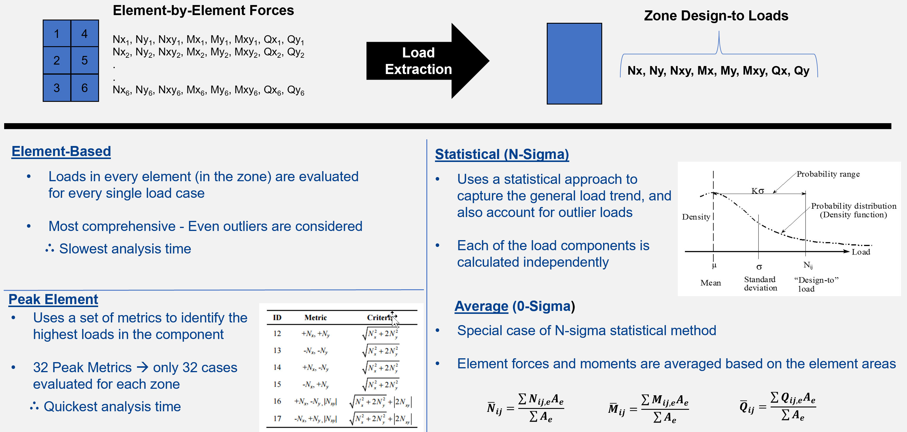
The user can choose from many different ways to identify design-to loads for their zones. Many elements define a structural zone, and every individual element’s load can be used as the zone’s design-to load; alternatively, the user can choose an average of the elements’ loads, a statistical distribution of element loads, or the peak load of any element. For the peak load approach, there are 32 metrics defined to flag the elements and subset of load cases that represent the zone’s load.
The most conservative approach to size a structure is to satisfy the forces in all elements of a zone for all load cases. This element-based approach is valuable for analyzing a fixed design, but practical sizing often requires that the element forces are processed into a smaller set of design-to cases.
The selection of load processing approach is made with a load property. Load properties permit the user to choose different load processing approaches for different types of structures.

Load processing of element forces (stress resultants) into appropriate design-to zone forces.
By dragging and dropping Load properties onto the FEM zones, you have flexibility and visibility of specific load processing being performed on different locations on the FEM.
Panel Segments
Stiffened panel segments are defined from attaching skins and stiffeners. Failure analyses such as cross section crippling require that the skin and stiffener are treated as a system.
Innate to HyperX is its ability to accurately analyze many different shapes of stiffened panels. Neither skin nor stiffener are separate entities, but rather integrate to be one entity called a Panel Segment.
Analysis of stiffened panels requires that the skin and stiffener are included in the panel’s thermoelastic stiffness formulation, calculated strains and curvatures, and resulting stresses (unit forces) per plate or laminate object. Many different failure analyses also require the treatment of the skin and stiffener to be a cross sectional entity, such as crippling, beam-column, panel buckling, and bonded joint of the skin to the stiffener flange.
HyperX always performs the analysis and design sizing optimization the same exact way with panel segments, regardless of the FEM stiffened panel modeling technique used. Smeared panels and discretely meshed stiffeners are analyzed the same.
HyperFEMgen
Automatically generate a detailed local FEM from the global FEM for verification. HyperFEMgen™ will make the mesh, apply boundary conditions, and apply the global loads to the local FEM.

Benefit
HyperX’s smeared panel stiffness formulation accurately predicts forces in the stiffened panel cross-section segments, even without those regions explicitly modeled. Taking those segment forces, HyperX uses analytical equations to predict many different types of buckling failures.
To verify the accuracy of the predicted object forces and buckling eigenvalues, HyperFEMgen can generate a local FEM, in lieu of a user needing to manually create one. The user saves time because they do not have to extract the panel cross section dimensions, laminates, and particularly the loads and boundary conditions from the global FEM and apply them to the local FEM.
In Action
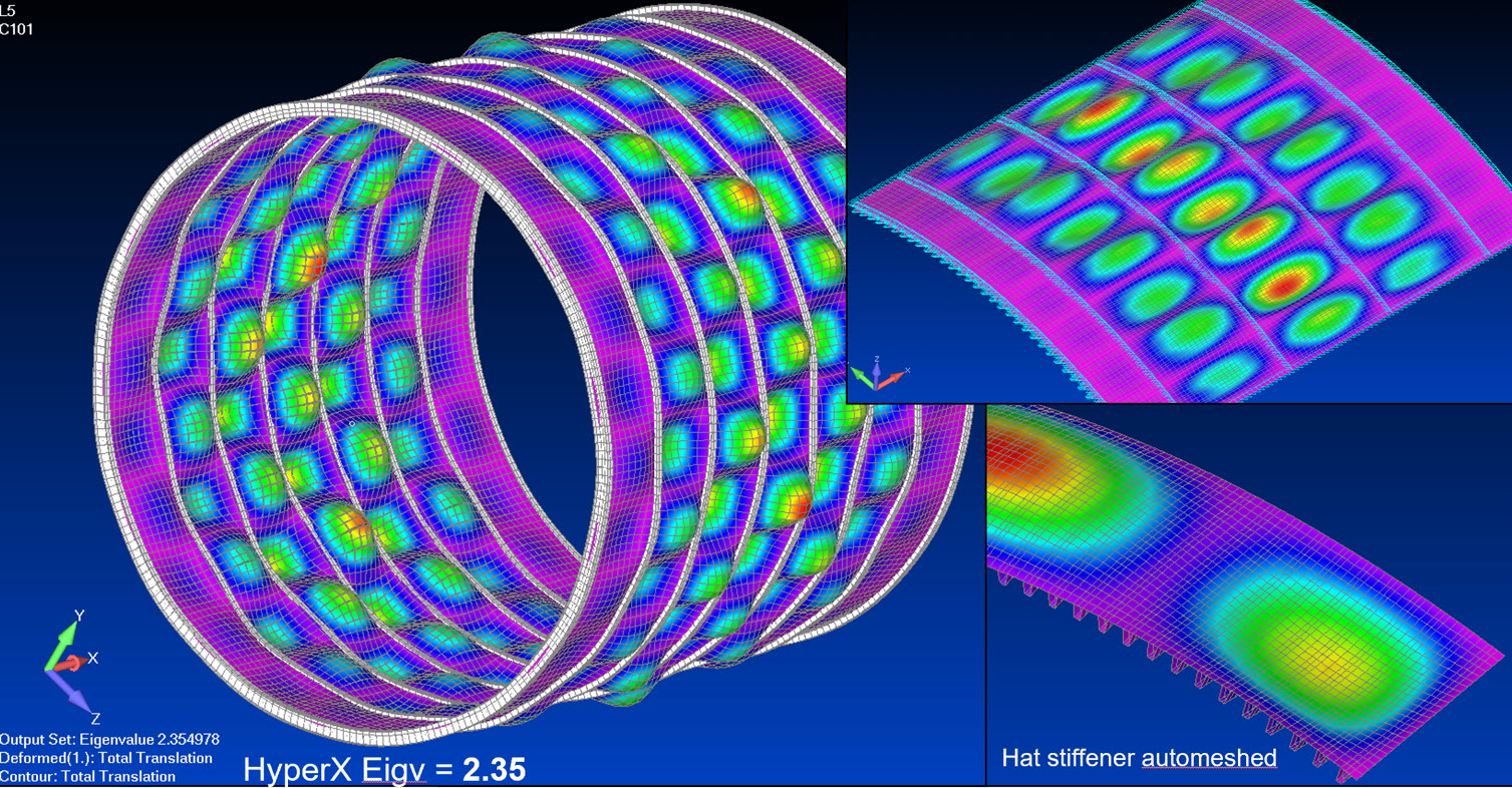
HyperFEMgen discretely meshes stiffeners with shell elements. If the global FEM is curved and/or has ringframes, this is included. Panel concepts consisting of open cross sections (e.g. Tee or I) or closed sections (e.g. hat) are both supported. For these optimized panels, their cross-sectional shape and laminates are automatically assigned to the local FEM.
The user selects a load case from the global FEM and HyperFEMgen will determine the magnitude of Nx axial, Ny transverse, and Nxy shear to apply to the panel edges, as well as the challenging boundary conditions to match the same internal forces of the global FEM. Equilibrium of forces and strain compatibility are satisfied.
Models can be output in both Nastran and Abaqus, with significant user control over the FEM generation. Users can dictate mesh density including element sizes and aspect ratios, select which material properties to use (tension / compression / average modulus), choose to include cutouts, and more.

HyperFemGen generated meshes with applied loading, boundary conditions, cross section stiffener dimensions, and laminates from HyperX results make these local models.
Contact Us
This site is protected by reCAPTCHA and the Google Privacy Policy and Terms of Service apply.
