Design Workflow
Design sizing optimization of acreage surface panels and fastened and bonded joints. Improve producibility, reduce weight, and resolve negative analysis margins of safety.

Feature Pages
Introduction
“Mojave-based Scaled Composites, which is building Stratolaunch, began using Collier Research Corp.’s HyperSizer design software at the start of design in 2011.”
“The designers of Stratolaunch faced a daunting task when they set out to conceive an aircraft that could fly to the stratosphere and release a launch vehicle that could weigh up to 250,000 kilograms, including the satellites it carries. The largest aircraft in the world needed to ensure that the design of the plane’s massive [composite] wings and fuselage weighed no more than necessary to meet safety and manufacturing requirements.”
Steps
- Use a HyperX database template that contains your standardized analysis, design, and load properties; and your materials
- Import the FEM (See FEM workflow) and
- Auto convert FEM properties into panel and beam zones
- Assign Design, Analysis and Load properties to the zones (drag and drop onto the FEM)
- Size and visualize dimensions and layups
These steps, from FEM import to producing aerospace design results satisfying all load cases, can be performed in a matter of minutes, even for large models.
Design Property
Use Design Properties to select between rapid sizing, detail sizing, or analysis only. Identify material, laminate and optimization bounds per variable.
The design space for sizing is defined with Design properties. When used, you get immediate and interactive feedback allowing you to complete a design in substantially less time.
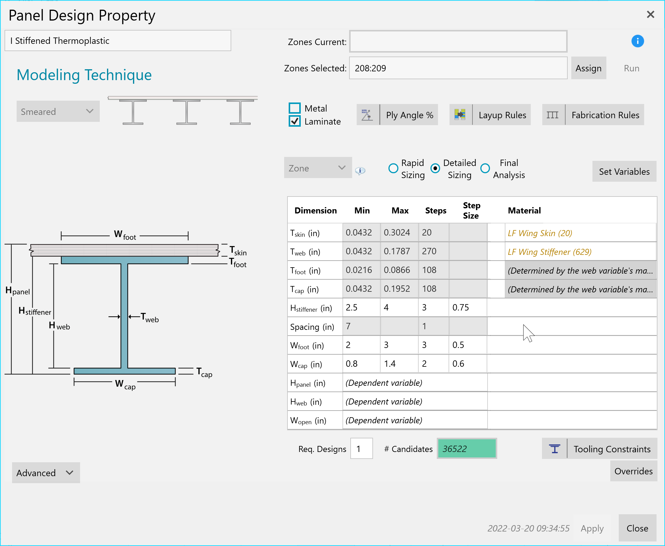
Parametric Detailed Sizing using Laminate Families. With 20 skin and 629 stringer laminate candidates, along with the dimension variable steps, 36,522 candidate I shaped composite panels will be evaluated during optimization.
By dragging and dropping Design properties onto the FEM zones, you have flexibility and visibility of their assignment on the FEM. Use them to quickly trade materials such as metal vs composite, or panel concepts such as stiffened panel vs honeycomb sandwich, or fastened vs bonded joint. They are used to evaluate the performance of thermoset vs thermoplastic and different Laminate Families. You can change Layup Rules to quickly quantify design impact on weight and the individual ply shapes, surface coverage, and drops/adds
Conveniently categorize and maintain them in the project tree. Along with Analysis and Load Properties, include them in a database template to share with others on your engineering team.
Design properties are similar to FEM properties for the “Final Analysis” use case as they define material, laminate, and cross-section of a zone. For a joint they define the fastener type, size, and spacing. However, when sizing they are much more than a FEM property as they identify variable min and max bounds to search for a viable result.
Sizing
The simplest design properties are those for panels in “Rapid Sizing” mode. In this non-parametric mode, only materials are required to be defined and the software will automatically determine optimum dimensions. For “Detailed Sizing”, a parametric mode, the design includes values such as minimum and maximum thickness for a plate, or heights and flange widths for a stiffener. For composites, materials can be effective or discrete laminates, as well as laminate families. For metals, users can select one or more metal materials.
Rules
Design properties allow the user to add additional restrictions. Common composite design rules like symmetry and balance, as well as ply count limits and adjacency rules are available as well. See page Composite Laminates

Each stiffened panel laminate segment has input for setting it ply angle % bounds (left) and layup rules (right).
For stiffened panels, additional producibility controls are available. These allow the user to define infeasible combinations of stiffeners and skins that are unmanufacturable, or violate a design principle for instance when the stiffener is too small (RSA ratio) to arrest a skin crack.
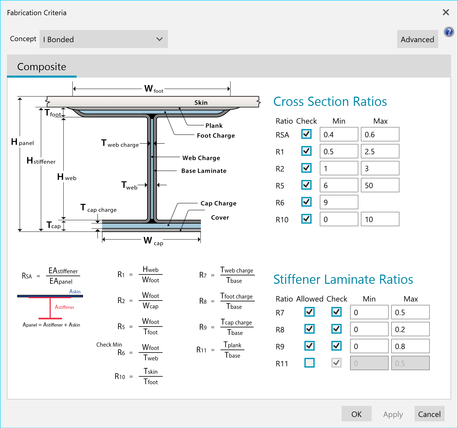
In addition to strength and stability, sizing has to also satisfy user specified geometric ratios.
Concepts
More than sixty different design concepts are available for panels, beams, and joints. For panels, these include unstiffened options like plates and laminates, core panels with foam or honeycomb, and stiffened panels with open and closed cross-sections.
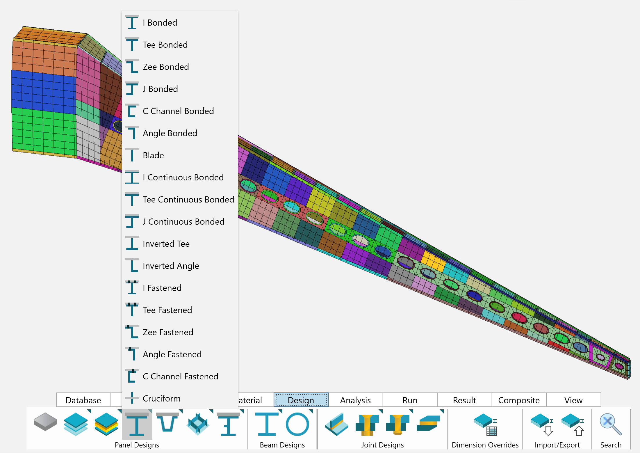
Open cross section stiffened panels you can select to apply to the FEM.
Material Database
Store material data in HyperX to use in analysis and sizing. Establish sophisticated laminate allowables, bearing-bypass envelopes, and correction factors in a shared database to deploy to team members.
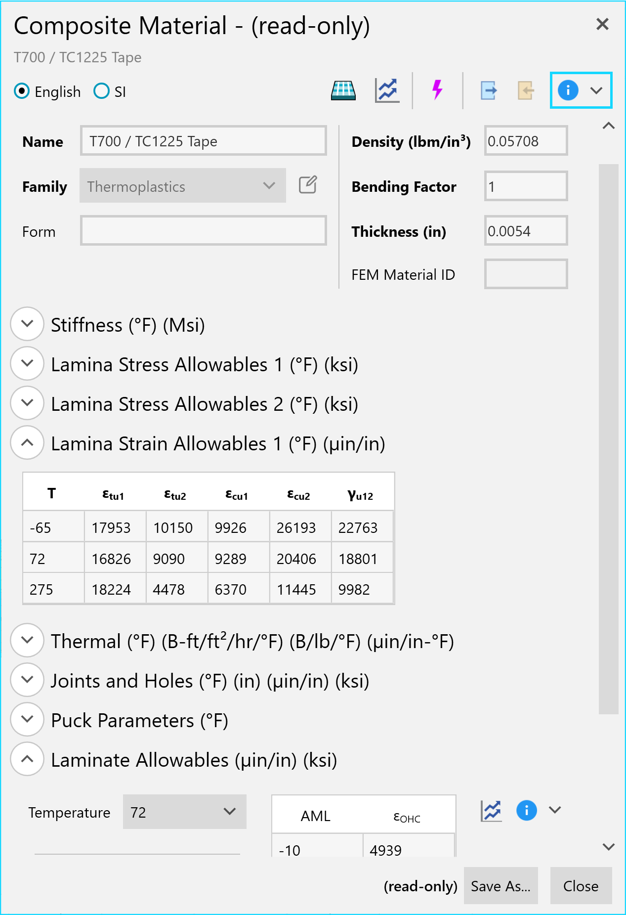
Composite material form organized by data type. You can expand table view data view for many data types. Button click capability to plot any data type.
HyperX supports the five major material systems found in aerospace design:
- Metals
- Composites
- Honeycombs
- Foams
- Adhesives
For each material type, all relevant material properties – stiffness parameters, stress allowables, thermal expansion coefficients, etc. – are stored. Temperature dependence can be enforced on any variable. For any other variable relationships, or to correlate with test data, correction factors can be applied as needed.
The database provides a way for organizations to store all structural material data – whether obtained from public sources or internal test programs. The HyperX install database comes pre-populated with some common aerospace industry materials defined. Each material contains properties found in vetted public sources. All engineers have access to this data and can use it in analysis and sizing.
All material forms are compatible with Excel, allowing for quick import and edits, as well for export to supplement certification reports.
Aerospace Required Data
Materials are fundamental to design in HyperX. The material definition in a typical FEM includes only elastic moduli, density, and basic allowables. The database allows the user to store additional material data types required for aerospace stress analysis and design.
In addition to the basic ply-level stress and strain allowables, laminate allowables as a function of AML or ply percentage (including complex polynomials) can be entered and used for sizing. HyperX also supports empirical bearing-bypass envelopes for composite joint analysis. All material data can be temperature-dependent, and HyperX will use the correct values based on the temperature of each design load case being analyzed.
In addition to temperature-dependency, users can enter correction factors to adjust material properties. These can be entered as constants or equation-based for ply and laminate properties. Available equations are functions of ply percentages, AML, and thickness. For bearing-bypass analysis, a tabular correction factor format is also supported. These allow the user to describe corrections as a function of multiple variables depending on what test data the user has available.
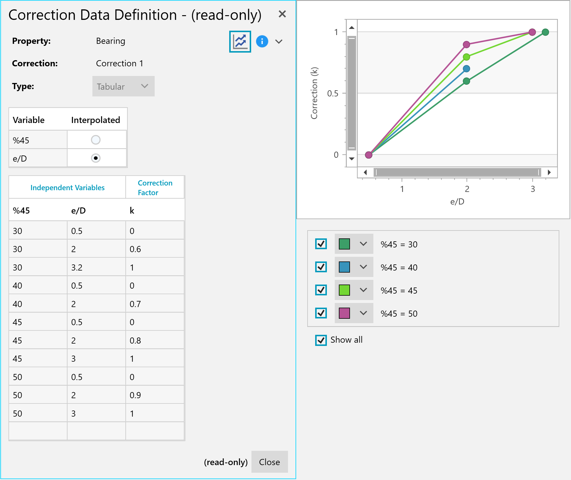
Data types can have correction factors. Shown are corrections to the bearing allowable.
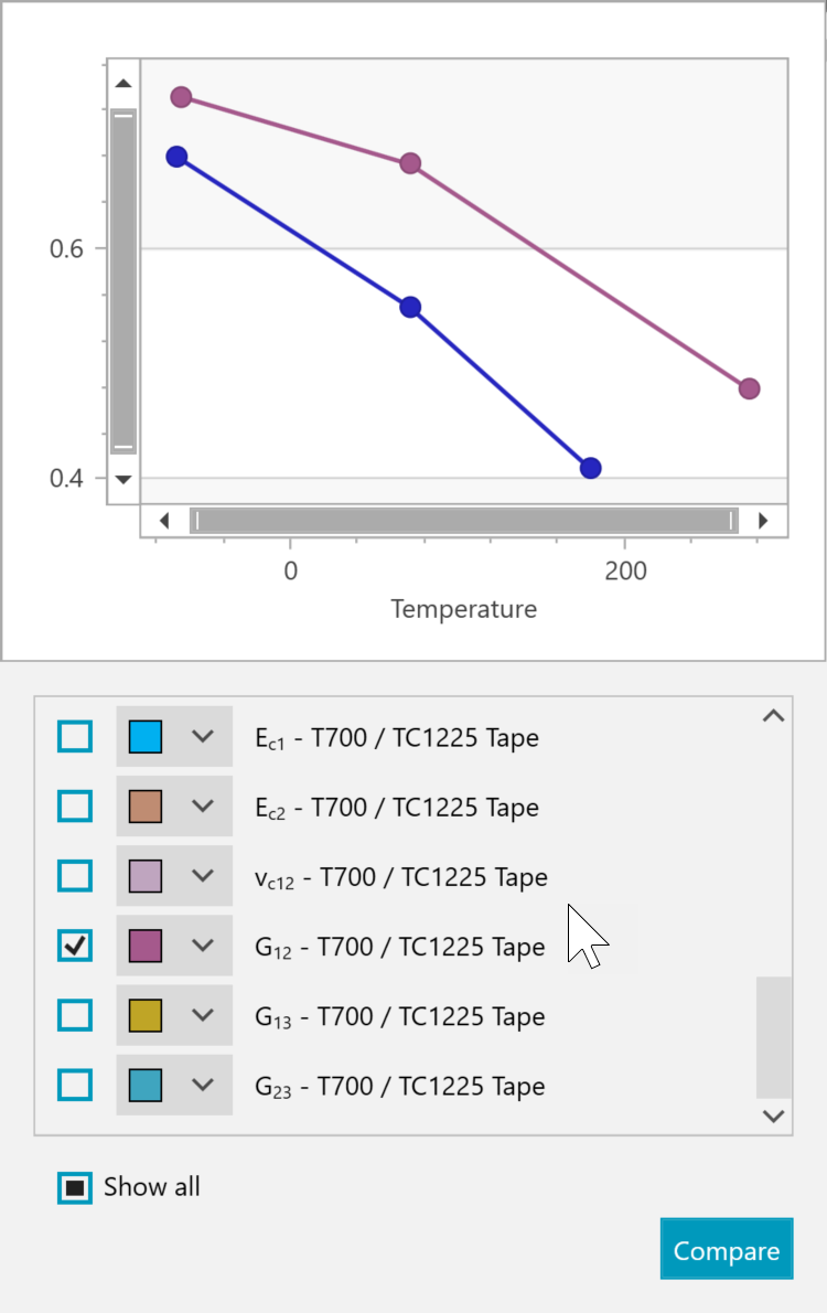
You can compare properties from many different materials in one view. Shown is a comparison of the G12 stiffness between a baseline thermoset and a thermoplastic.
Sheet metal stock sizes, as set by alloy suppliers, can be enforced for thickness sizing.
Fastener and Rivet Database
Store fastener and rivet data in HyperX for joint analysis and sizing. Define this data in one place and efficiently share among a team of collaborating engineers.
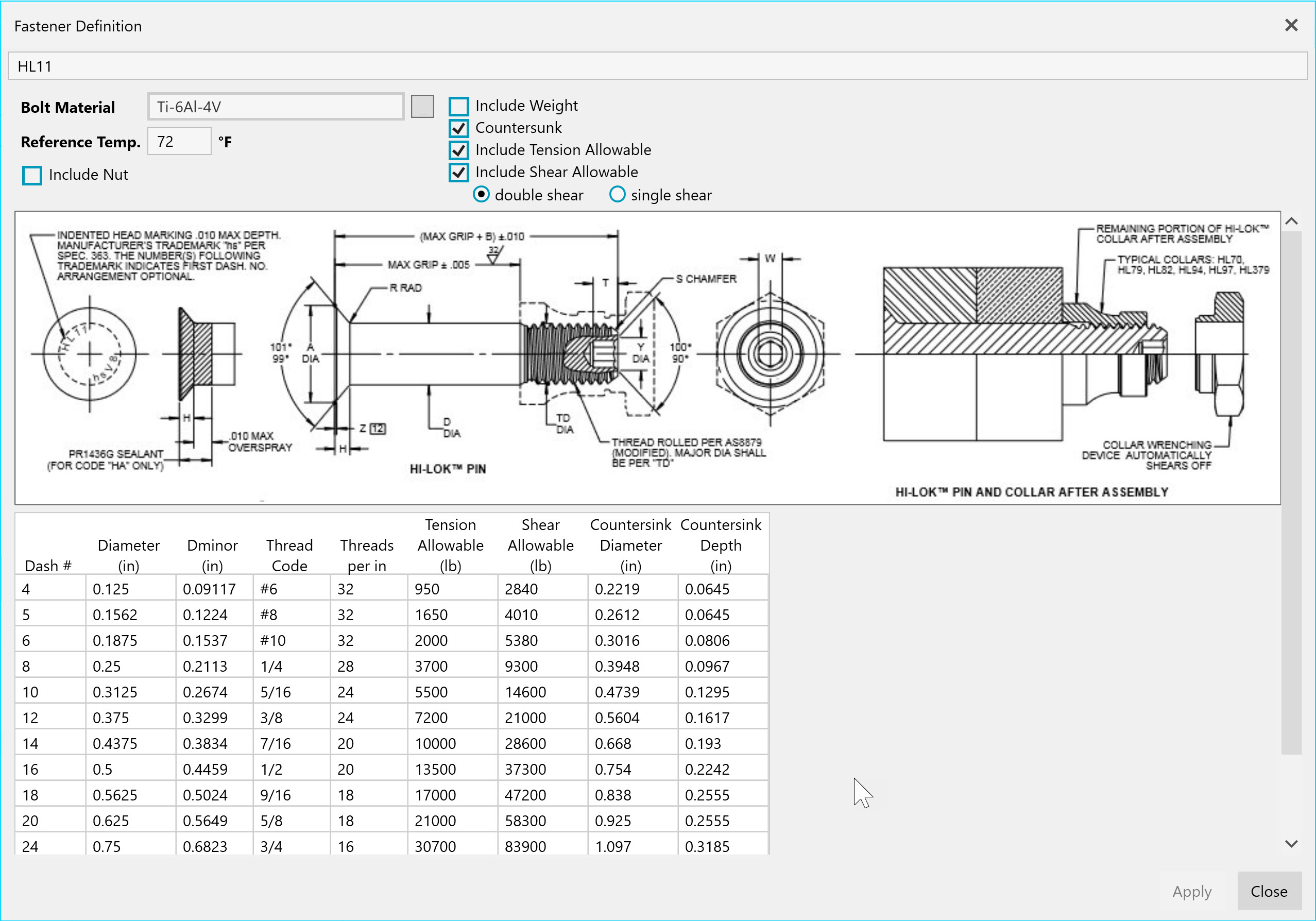
Example Hi-Lok fastener from HyperX database.
HyperX includes hundreds of commonly used aerospace fasteners and rivets with vetted, public-source data. Tension and shear allowables are used for analysis and sizing. HyperX will evaluate and find an optimum fastener for your structure.
Fasteners are displayed in a similar layout to vendor’s data sheets, providing familiarity to the engineer. The above is a Hi-Lok 11 fastener from the installed pre-populated database template.
Fasteners stored in HyperX can be managed by a single engineer and then deployed to the team – enforcing consistency for all. Fastener data can be manually entered or can be imported and/or updated using Excel spreadsheets.
Zone Generation
Zone Splitter
Split large FEM property areas into many analysis/sizing zones at geometric boundaries such as intersecting structure. Optimize zone shapes and sizes to load gradients.
FEM properties define regions of constant dimensions, material and laminate. As imported, the FEM properties may not be defined to the shapes and sizes needed for structural analysis and sizing. HyperX automatically separates FEM property regions into individual analysis/sizing zones.
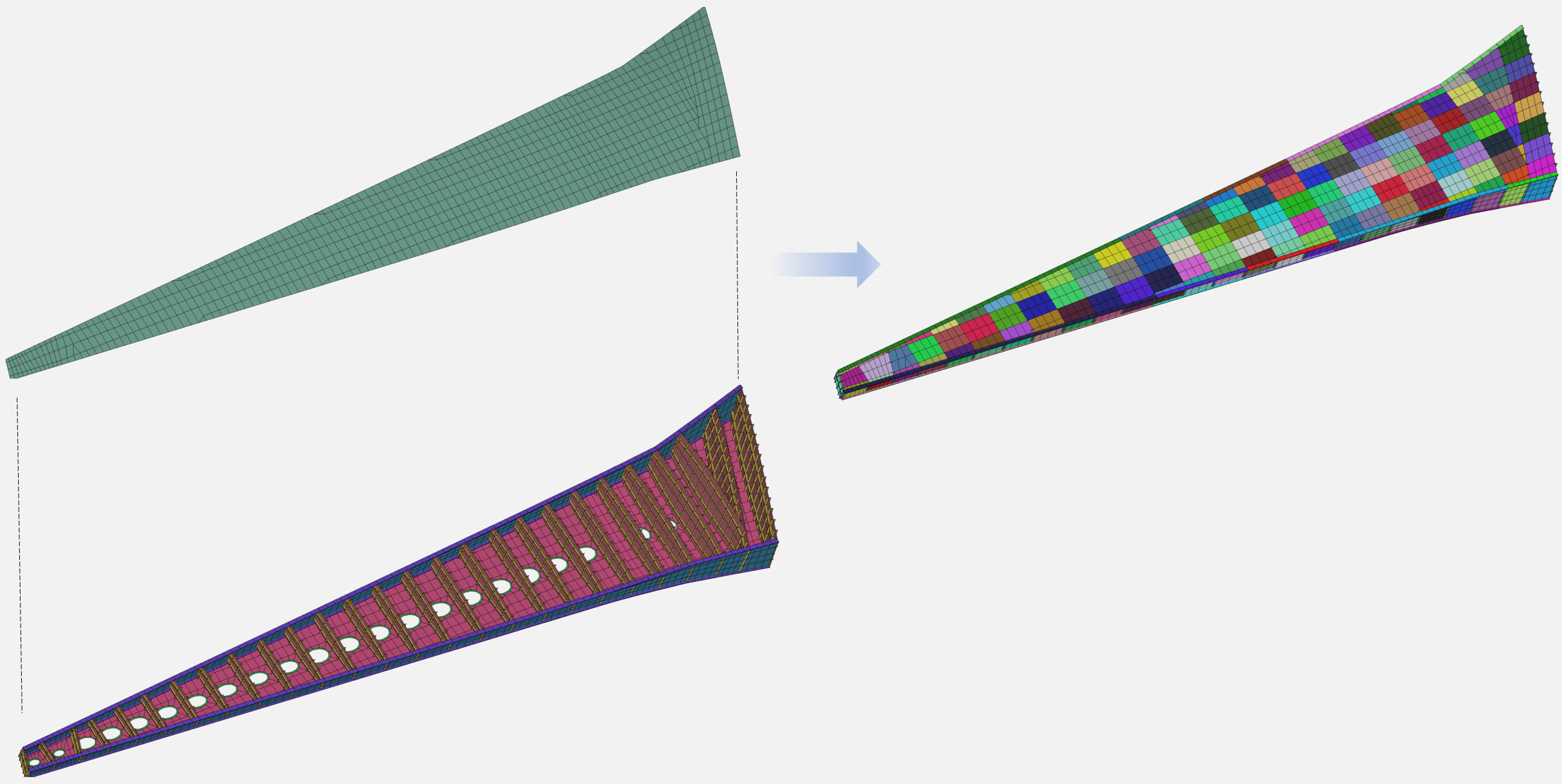
(Left) Wing upper skin surface represented with one FEM property PSHELL or PCOMP. (Right) Analysis and Sizing zones automatically split out to match the span distance between each rib.
HyperX can automatically detect intersections of ribs, spars, and stiffeners (Orthogonal Members) for this process. It can also separate zones into regular patterns based on width restrictions.
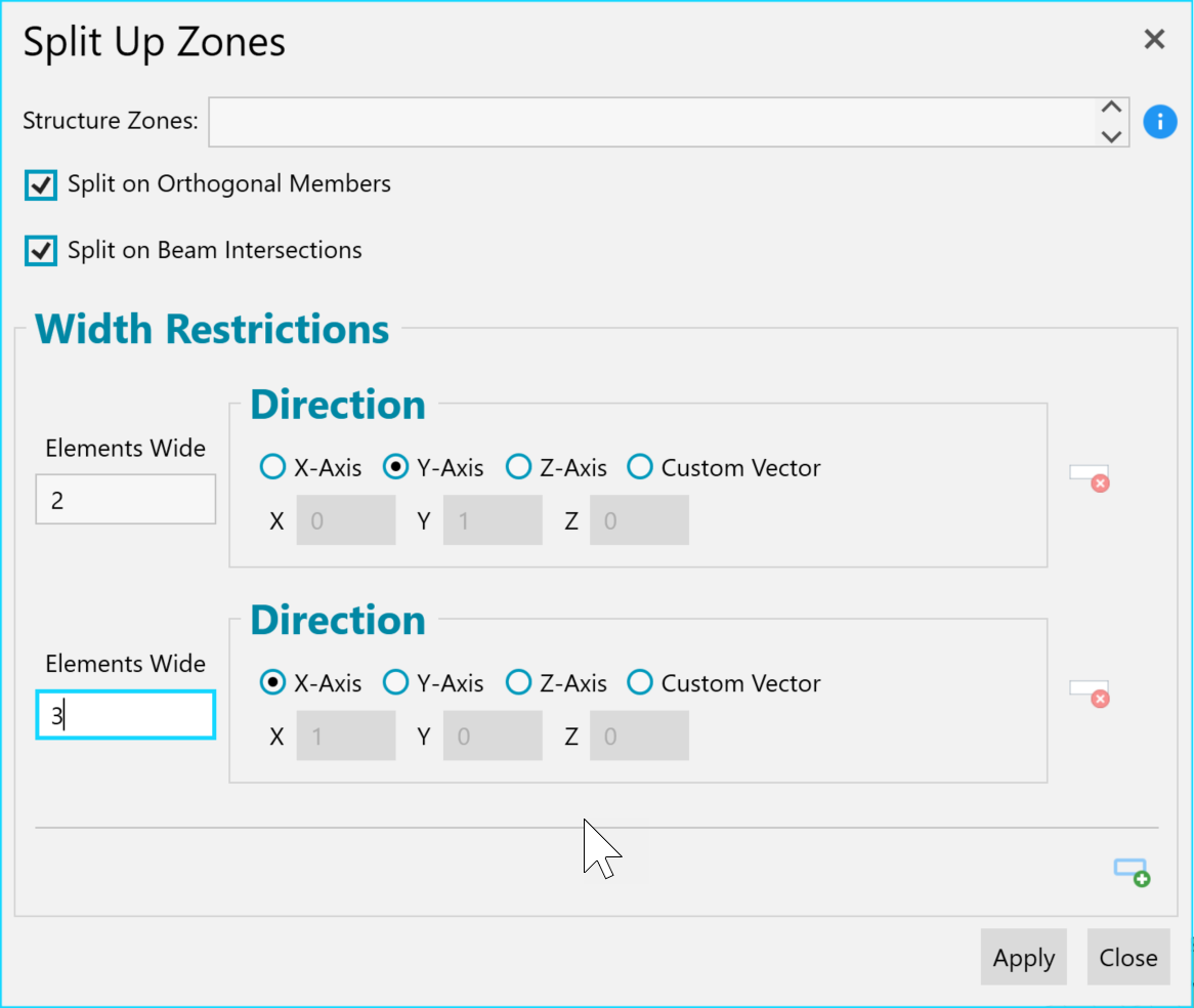
FEM zones automatically split out to be a required size.
This splitting process calculates new buckling spans for buckling analyses. Even if zones have the same design, margins of safety must be computed and reported for each.
Zone Optimization
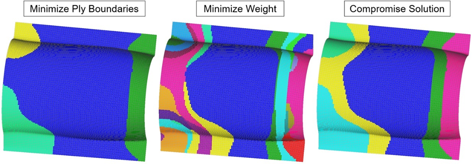
When the size and shape of zones are more flexible, HyperX can optimize organic zone shapes. When sizing laminates, sandwiches, or plates, HyperX creates new zones based on the collections of elements that optimize toward similar dimensions and laminates. Highly-stressed regions may thicken up while lower stress ones thin out into organic shapes. You can control the compromise between minimum weight (many irregular zones) and higher producibility (larger, smoother zones).
Section Cut
Calculate cross-section stiffnesses, center of stiffness, and shear center. Apply minimum values that are enforced when sizing. Report summation of “built up” section cut loads, per loadcase.
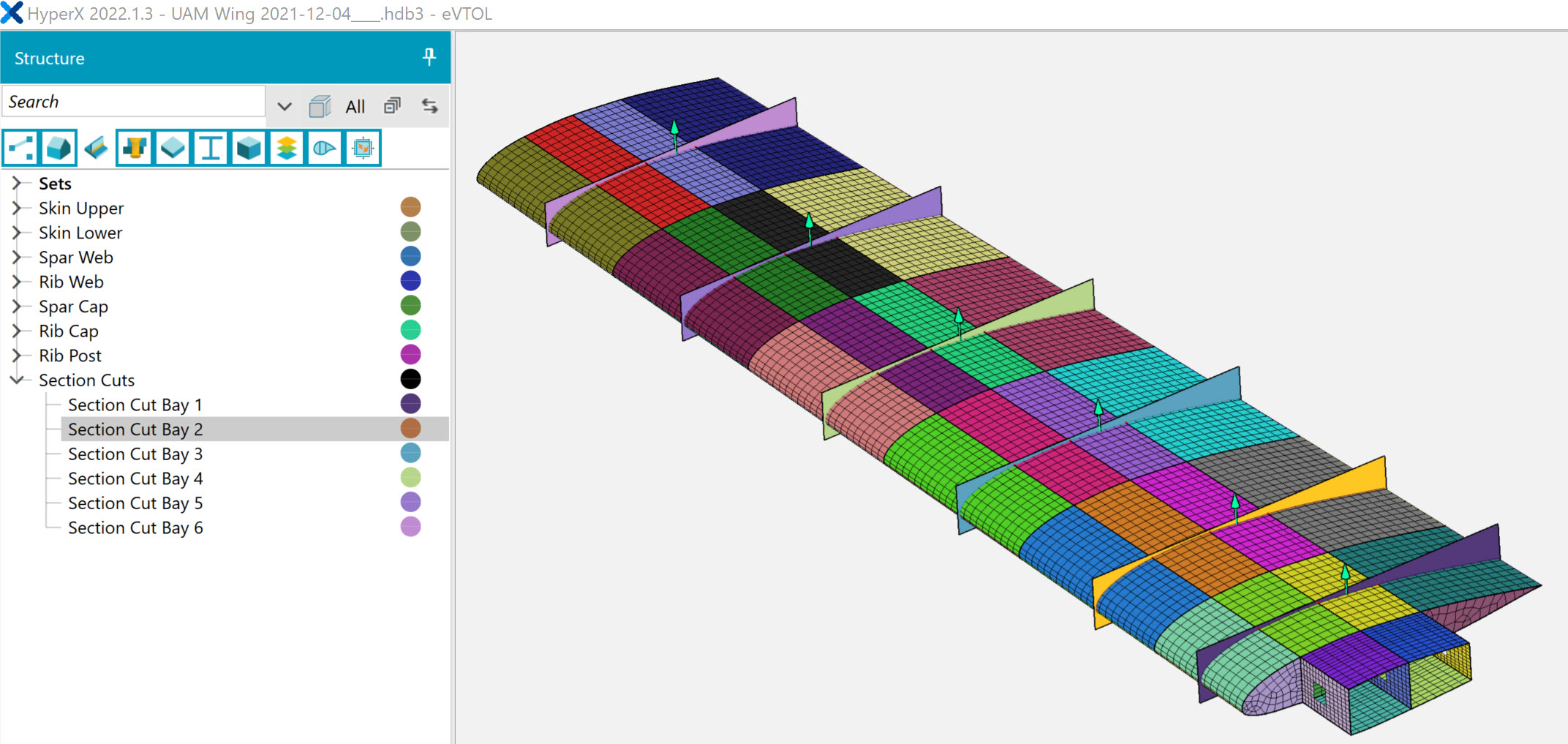
Section cuts made were made at the centerline of each panel bay. Cuts in the viewport are interactive with the tree. Section Cut Bay 2 is selected from the viewport.
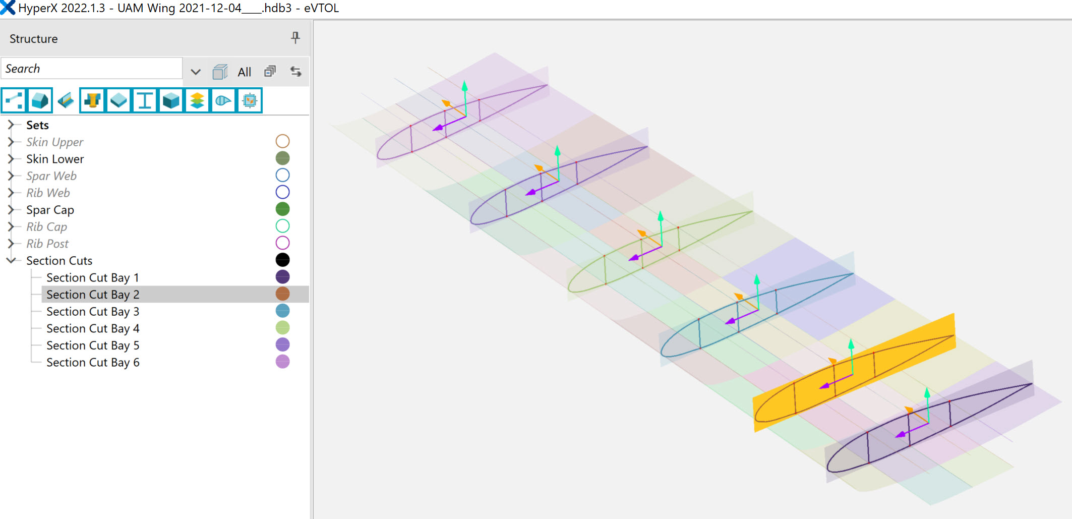
A transparent view.
Section cuts are important for aerospace structures. They are used for analysis and optimization of a built-up beam or entire structure cross section to required EI and GJ values.
HyperX allows the user to create section cut planes at any location and orientation to visualize the cross-section outline, center line, and vector axes.
Section cuts are visible in a planar 2D perspective and in the 3D viewport. They are listed as nodes in the tree, and can be organized and interacted with like other HyperX entities such as joints and zones. Edit them by either clicking from the tree or from the FEM viewport.
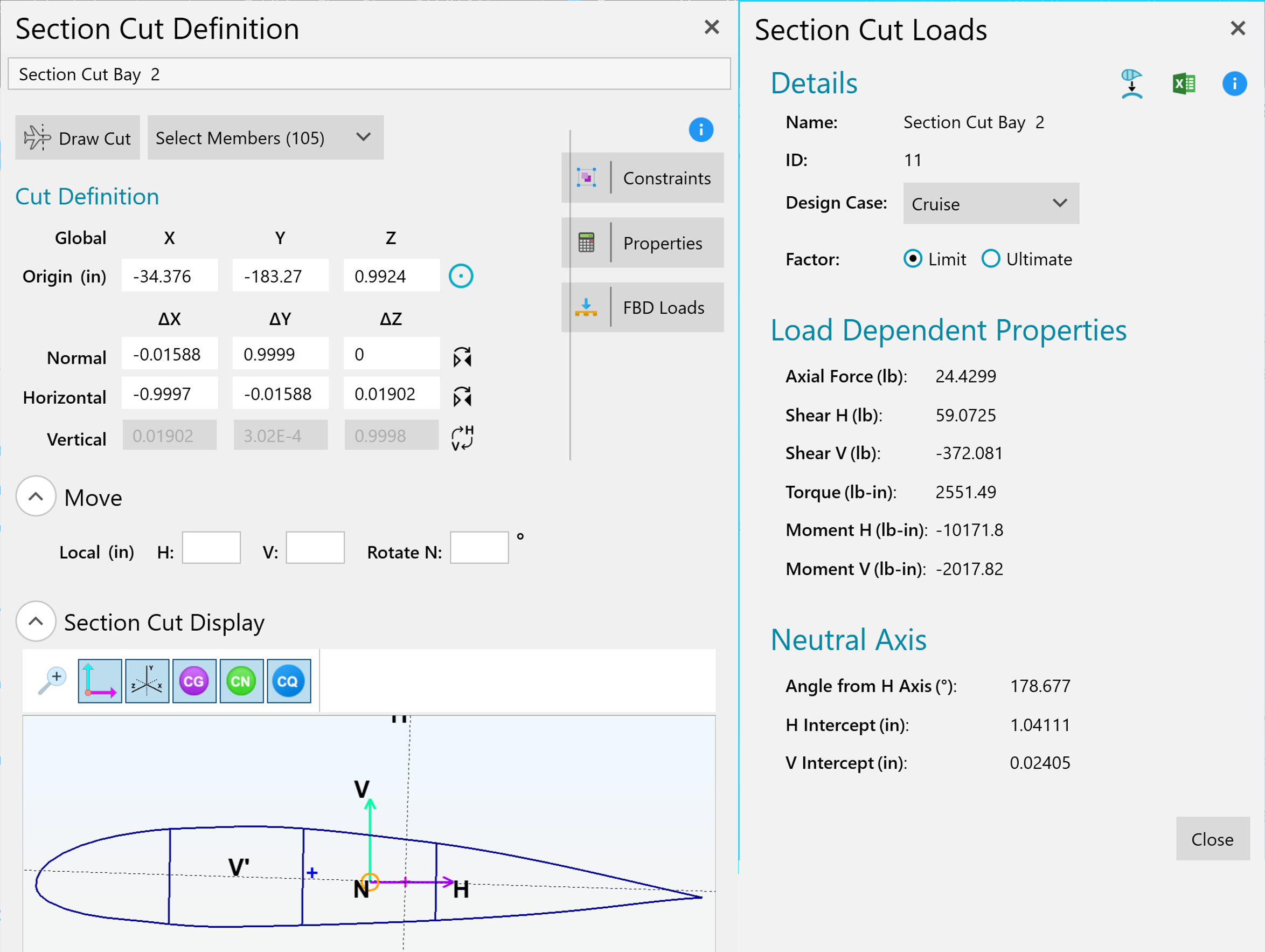
Form showing 2D plan view of Section Cut Bay 02. From this form is a summation of Free Body Diagram forces per load case.
Force Reporting
Section cuts extract element forces from the mesh, adds them together, and reports resulting free body forces, per design case, at any number of arbitrary cut planes.
Stiffness Reporting
The section cut’s flexural rigidities (EI) and torsional rigidity (GJ), as well as the center of gravity and shear center are computed based on sizing and analysis. All values are accurately calculated – even for arbitrarily complex cross-sections with a combination of shell and beam elements. The cross section can be open or enclosed with any number of cells.
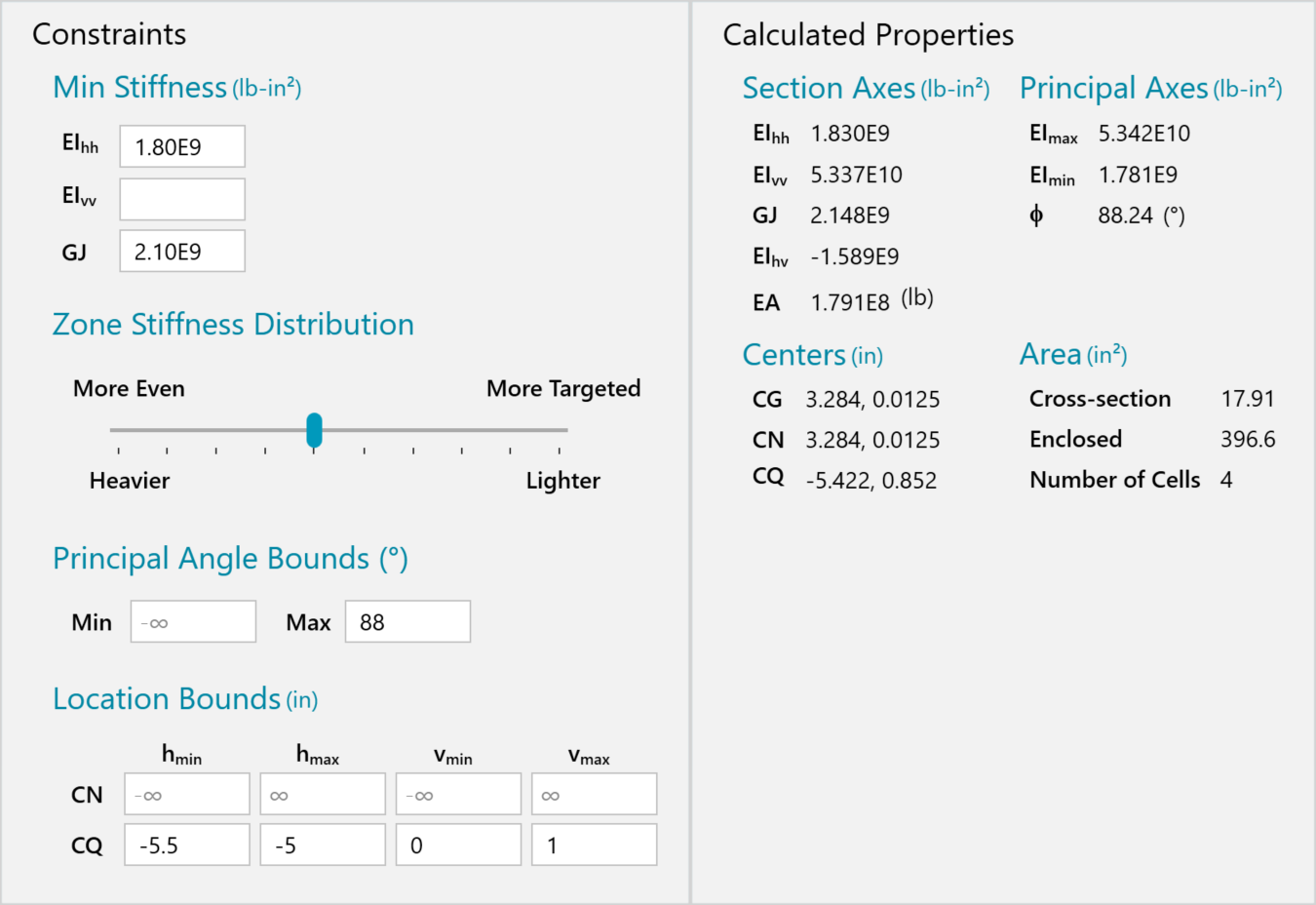
Constraints on the left and resulting calculated properties on the right.
Stiffness Optimization
Users can set minimum required values for EI and GJ that are enforced when sizing the structure. HyperX uses a gradient-based optimization technique to satisfy multiple stiffness requirements simultaneously to satisfy values quantified from external sources, such as aeroelastic analysis.
Additional constraints can be imposed such as a principal angle min and max bound, and bounds for where the location of the center of stiffness and shear center (CQ) must reside.
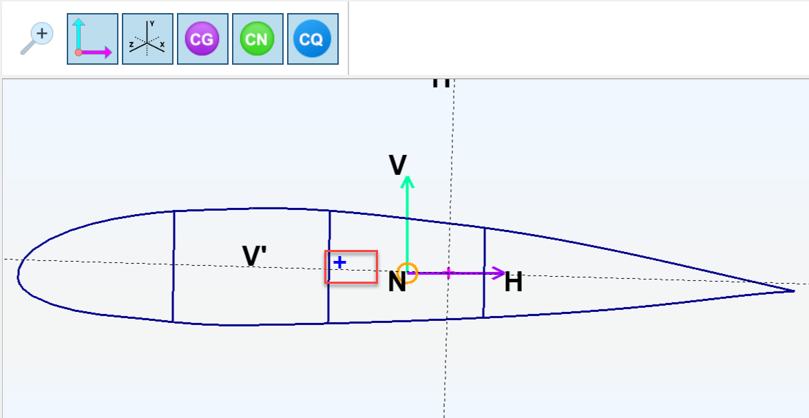
User defined bounding box, noted with red box, where the shear center (blue cross) must reside.
The section cut stiffness optimization is performed simultaneously with typical strength and stability criteria for panels and beams. The slider, as seen in the form, provides the user the ability to adjust how concentrated to allow the stiffness optimization to perform. All the way to the right and the lowest possible weight to achieve the stiffness criteria will be found. This may cause some of the structure to get big while other parts do not grow at all. By inspection, for instance, the spar caps may get very thick and by moving the slider to the center, a solution will be found where the caps get less thick by requiring some additional stiffness in the surrounding skin panels. In all cases, the cut sections will also simultaneously satisfy all stress failure analysis margins of safety.
Built-up Beam Tool
This tool extracts free body loads from the mesh, converts them into summed beam loads, localizes the loads to a HyperX beam concept (I, Tee, C channel, etc) analyzes and sizes the beam flanges and web thicknesses, widths, and heights using beam failure criteria.
This built-up beam section tool is useful for applications such as a wing spar that has shell elements discretely modeling the spar caps and webs, with a need to analyze as a beam. Particular for this scenario is to sum FEA forces of the spar web shell elements to derive its in-plane bending moment. With this data, stress concentrations and buckling with tension/compression load gradients are correctly included.
Contact Us
This site is protected by reCAPTCHA and the Google Privacy Policy and Terms of Service apply.
