CAD/CAM Interface

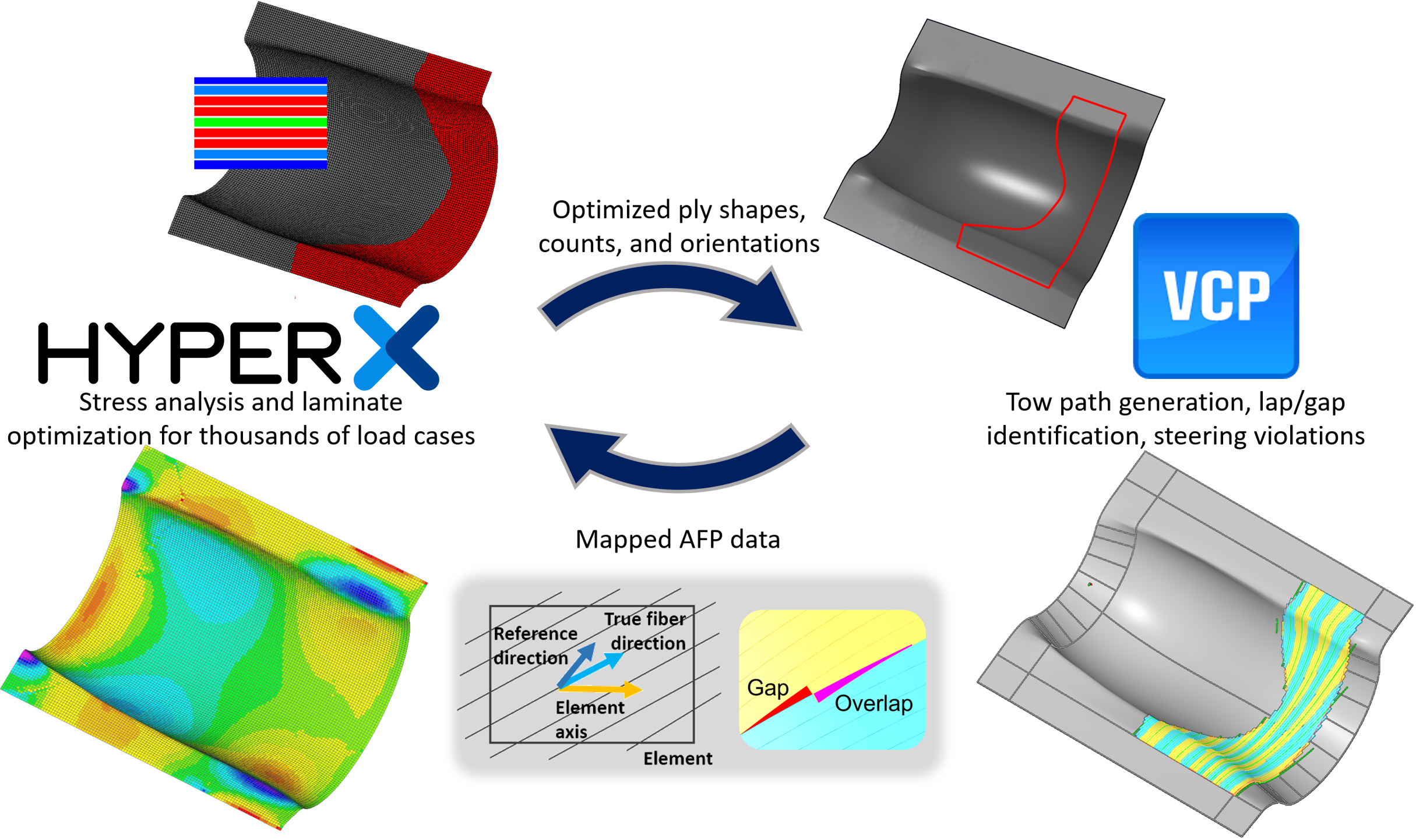
CAD and CAM software play a big role in generating producible designs. HyperX is able to read in CAM manufacturing data such fiber directions and export data such as optimized CAD ply boundaries.

AFP Data Import

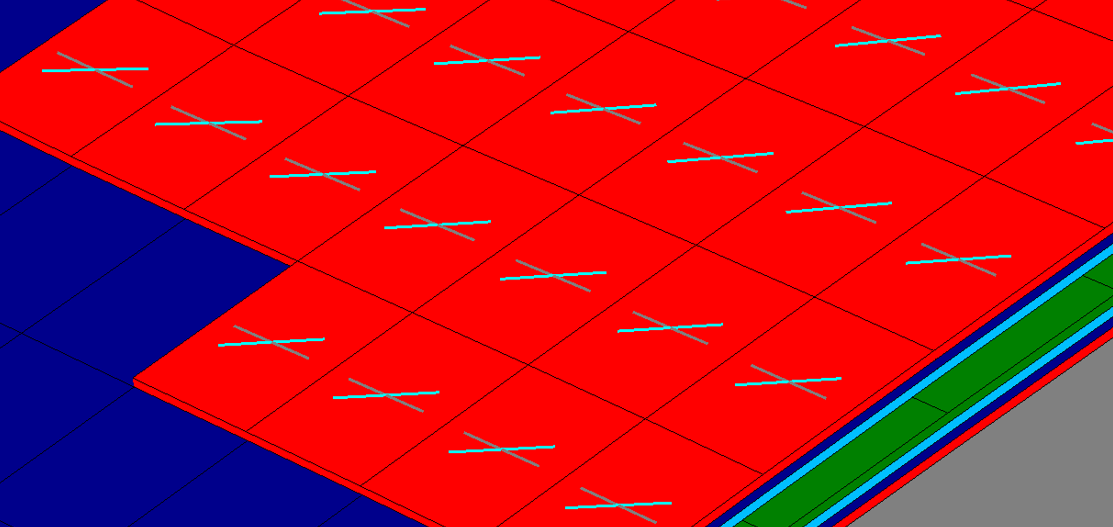
As-manufactured fiber directions and thickness for AFP structures on double curvature can vary from the original design. HyperX can import this data for re-analysis.

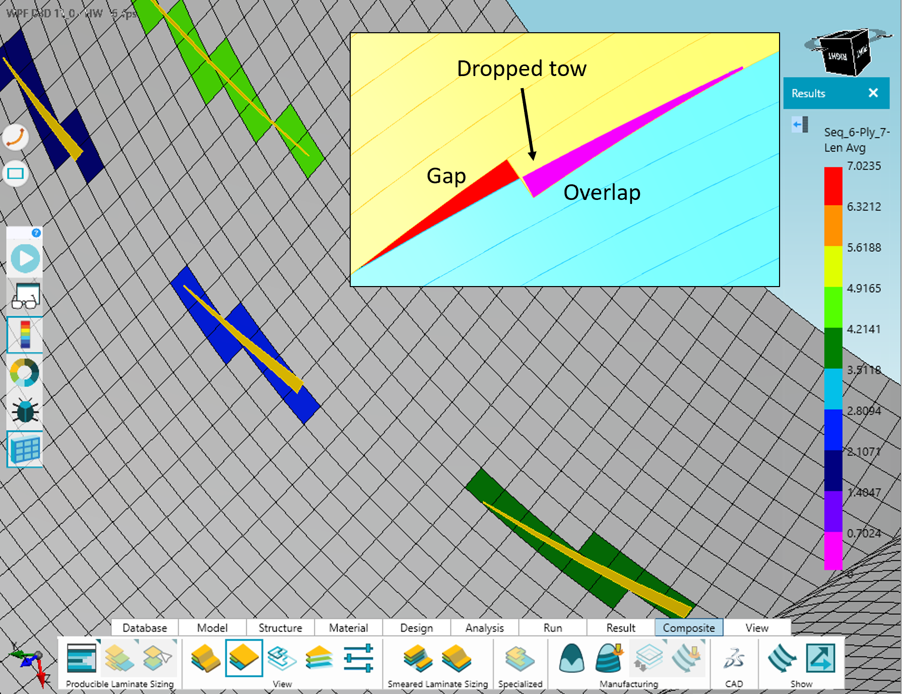
Although composites excel in applications with double curvature, manufacturing with Automated Fiber Placement (AFP) can introduce challenges with fiber alignment and overlaps and gaps (of individual tows in plies).

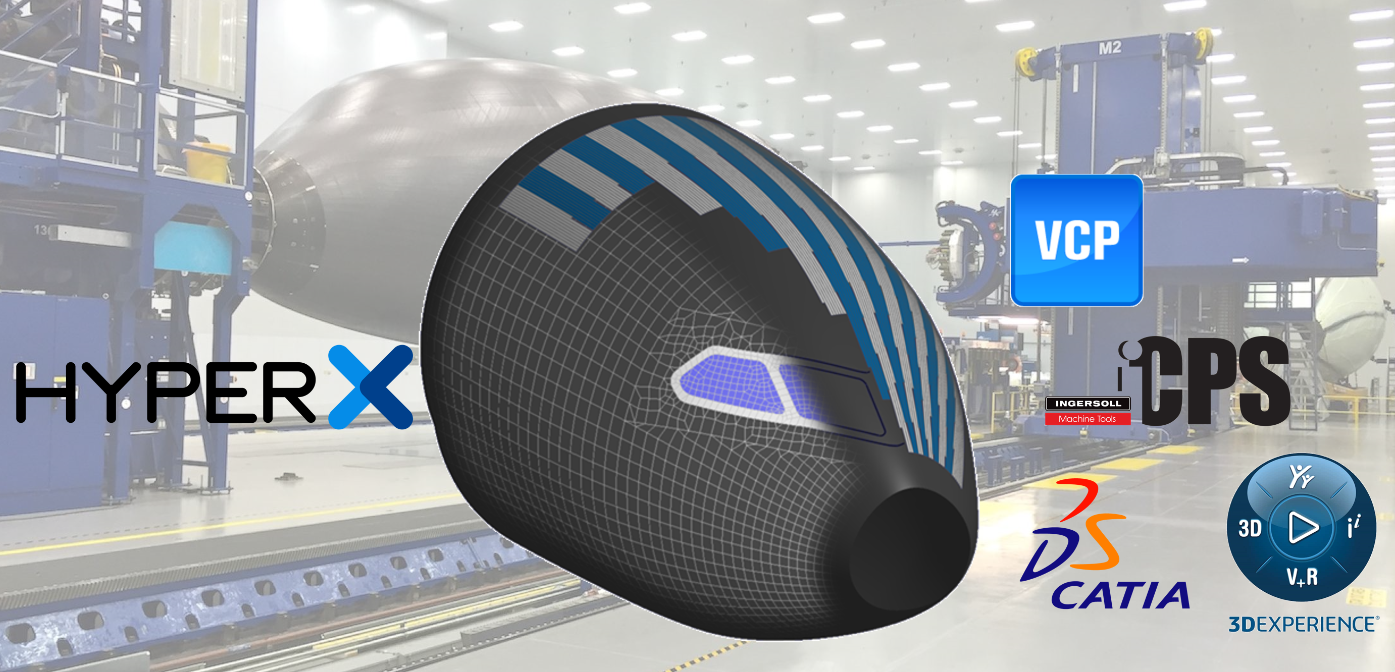
Fiber deviation is often introduced on structures with significant curvature because it is impossible to steer tows to achieve a desired uniform fiber orientation everywhere on the part without causing other defects such as wrinkling (local buckling) of tows. AFP process planners find fiber paths that are manufacturable, but may not line up with the original FEM fiber directions. HyperX can import fiber directions from VCP and iCPS software and include these fiber directions in lamina or laminate analysis.
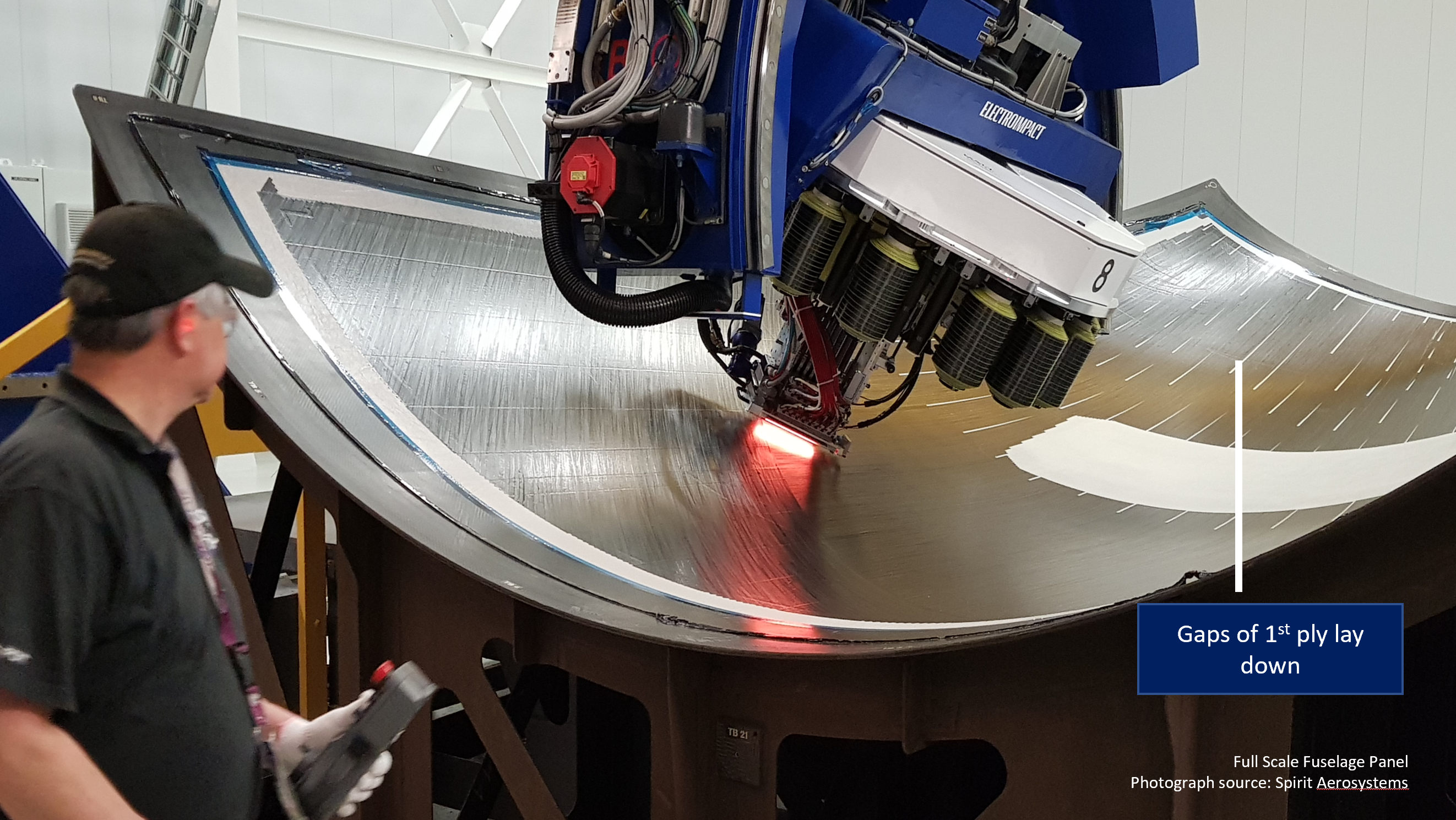
Tow overlaps and gaps are also common on curved structures due to convergence/divergence of tow paths. These features form intersection of machine passes and can result in increases or decreases of laminate thickness in these locations. HyperX can import lap and gap geometry to determine the impact on margins of safety caused by the thickness deviations.

CAD Boundary Export

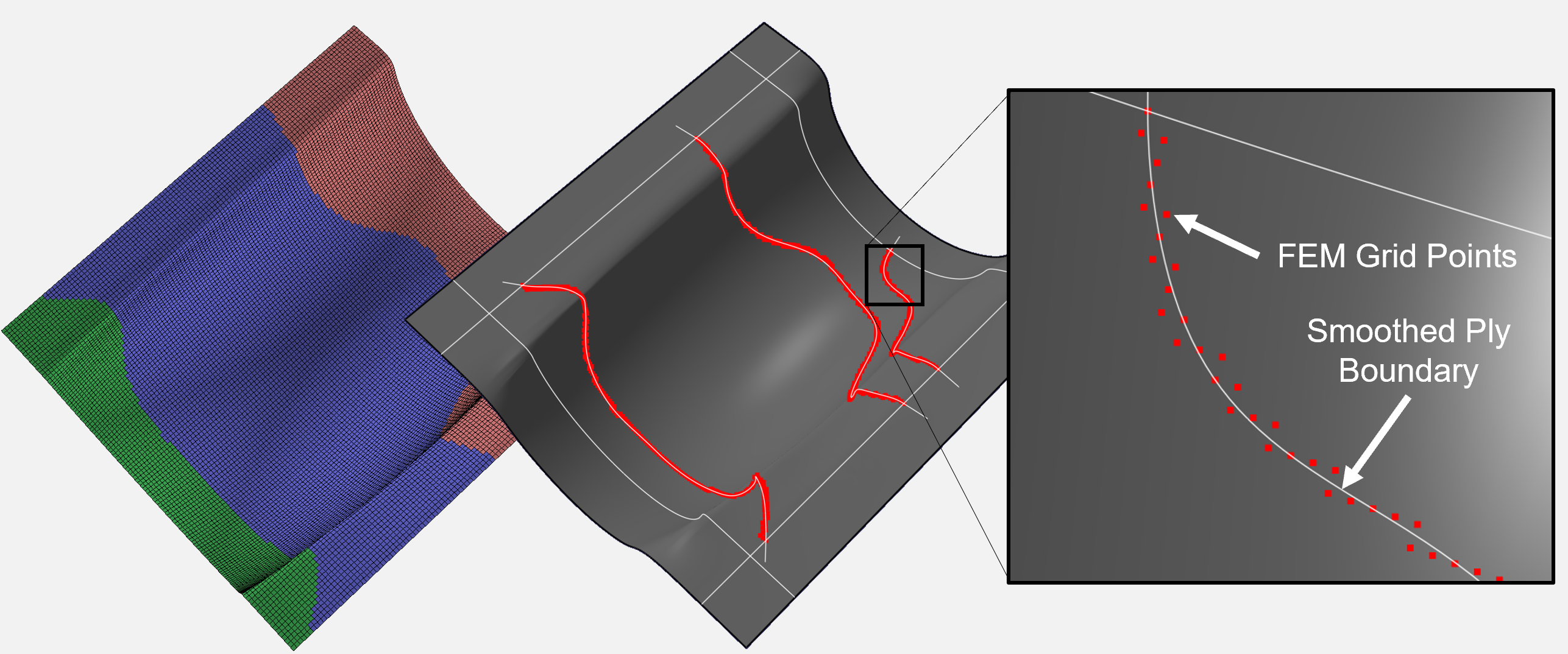
HyperX can optimize “organic” boundaries of plies and zones to suit structural loads. The boundaries of these zones or plies can be exported in a CAD format.

Exporting CAD boundaries from HyperX enables the use of ply shapes or metal thickness steps that were not previously defined on the CAD model. HyperX is able to determine the optimum boundaries for these features as dictated by internal loads. Once these shapes are defined, HyperX can export the grid points along the boundaries of these features in standard CAD formats (.igs, .stp, etc). This allows the user to create CAD boundaries (via curve fits or other methods) that exactly match the FEM definition, keeping the two domains in sync.

CAD Ply Export

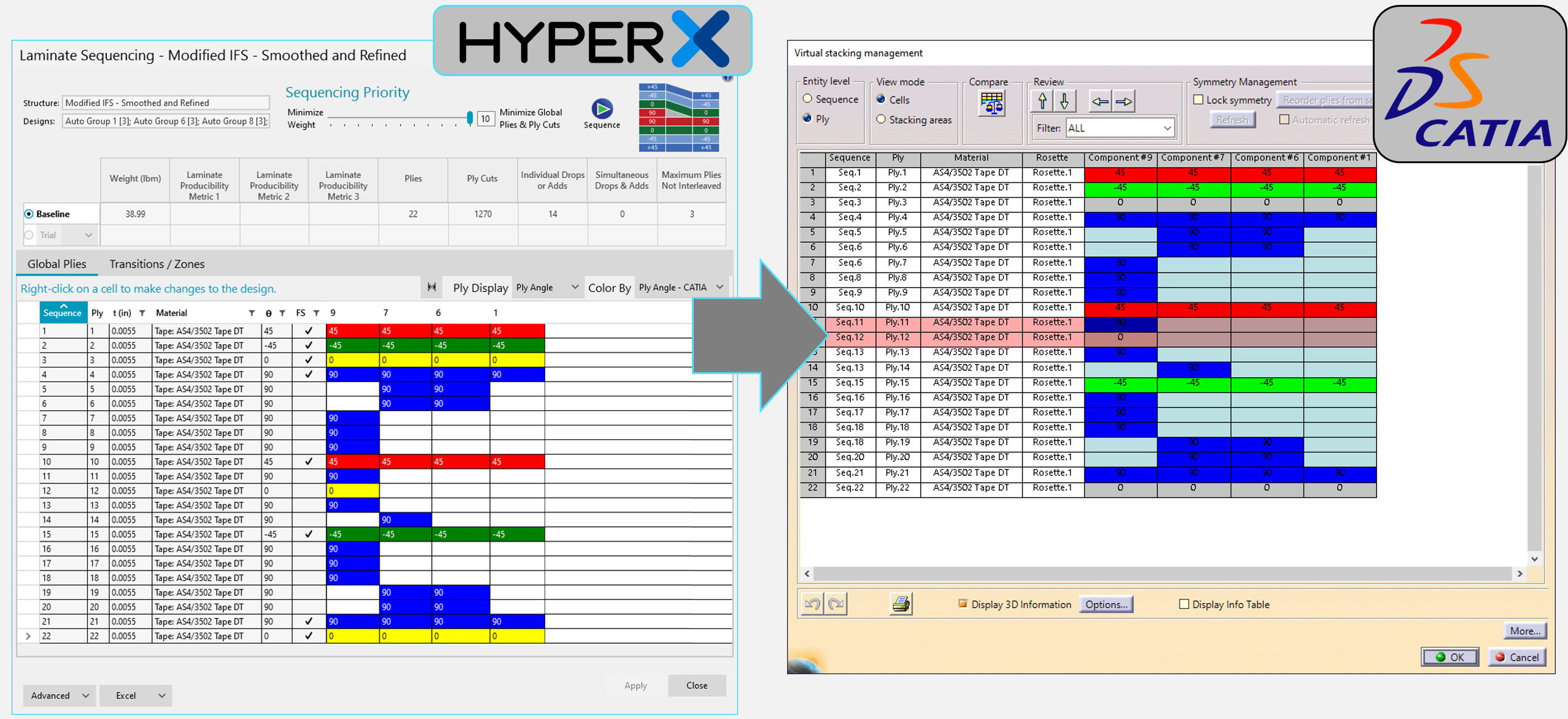
Plies optimized on the FEM in HyperX must be mapped to CAD software to be finalized for manufacturing.

HyperX can export ply tables in several formats, including CATIA and FiberSim. The ply table defines which zones are covered by each ply in each sequence. The table can be imported to the CAD software and used to create the final plies for manufacturing.

CAD Ply Export

Contact Us

Meeting Times

Please specify your areas of interest

Please specify your areas of interest for your Demo

What kind of partnership are you interested in?

This site is protected by reCAPTCHA and the Google Privacy Policy and Terms of Service apply.

Aerospace Structural Analysis and Design Optimization

© 1995 - 2023 Collier Aerospace Corporation. All Rights Reserved.