Sizing Optimization
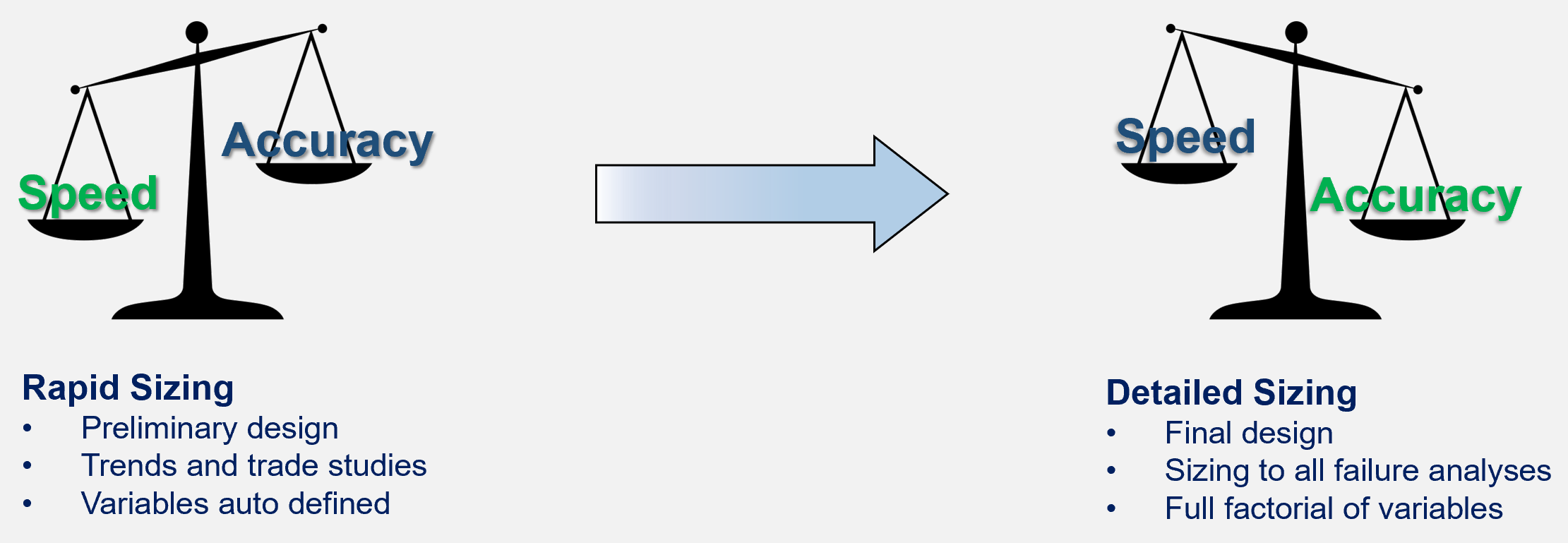
Panels, beams, and joints can be sized throughout design phases. Rapid Sizing is used early and detail sizing later.
Capability Pages
Introduction
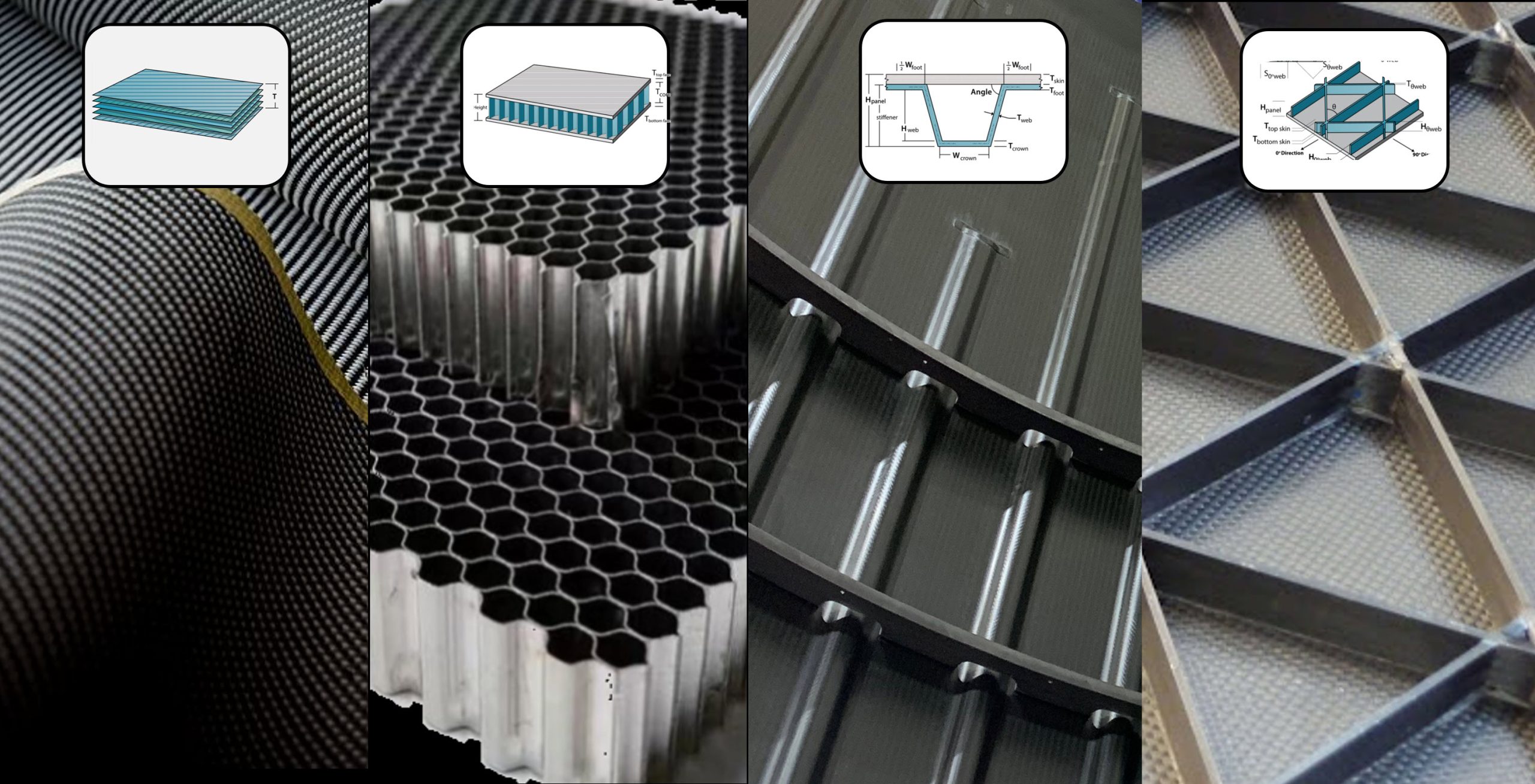
Lightweighting structure is important in many industries. Robust and proven sizing optimization for reducing weight of many different materials and panel concepts is a key benefit of HyperX, while also producing consistent and producible designs.
Sizing modes for all stages of the design cycle.
Rapid Sizing
In a few seconds size many FEM zones to all load cases with different materials and panel concepts. Variable bounds automatically set.
Benefit
Rapid sizing is a non-parametric optimization approach that does not require the user to define variable bounds like the minimum, maximum, and number of step increments per dimension. Nor does it require the user to define nor select discrete laminate stacking orders. For this reason, it is easier to use, and is often employed early in the design process.
Rapid sizing is available for metal or composite panels.
Analyses are for metal strength, composite ply based and laminate-based strength, panel buckling, local buckling, crippling, and displacement stiffness criteria.
In Action
Select any number of panel FEM zones and rapidly size to all load cases. Used for quickly identifying weight trends to upload to the HyperX Dashboard. Also used to generate design study pareto frontier plots.
For composites, it optimizes ply counts for each of the 0/45/90 ply angles – which is the same as optimizing laminate thickness and % ply angles in the 0/45/90 directions. For stiffened panels, it also optimizes the Dij bending stiffnesses to satisfy skin local buckling.
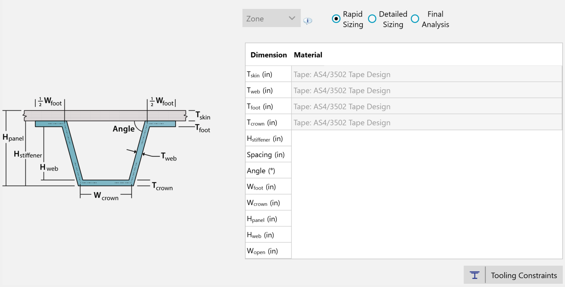
Rapid sizing input is super simple. Just enter a metal or ply material. Example form is for a composite hat stiffened panel.
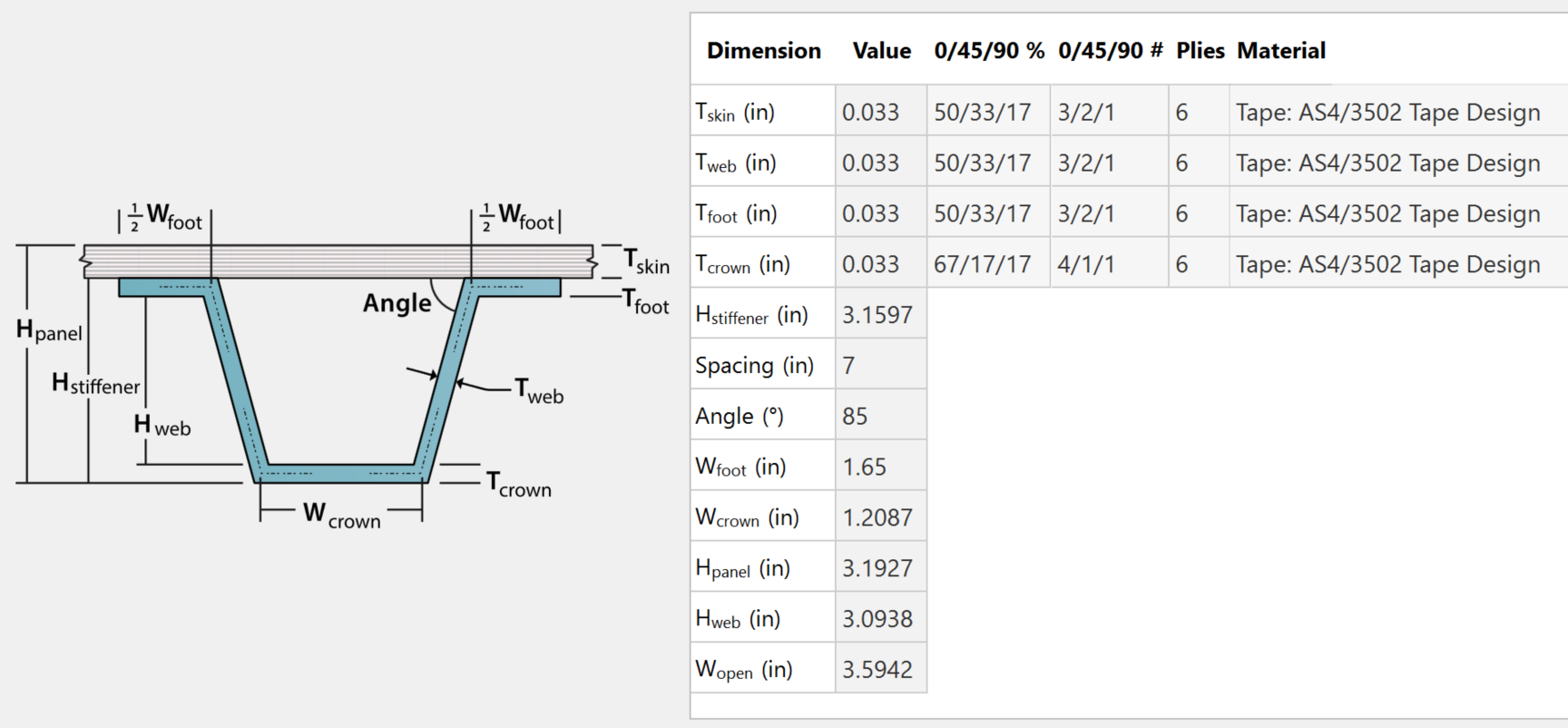
Rapid sizing results output is optimum dimensions and ply counts in the 0/45/90 angles.
Detail Sizing Panels
In a few minutes rigorously size many structural zones to all load cases with different materials for a given panel or beam concept. User controls variable bounds.
Benefit
Detailed sizing is a parametric optimization approach that does require the user to define variable bounds like the minimum/maximum value per dimension. Though requiring more expertise in setting up proper variable bounds, it provides more user control over each individual variable min and max limits, and the step size increment. It is often used later in the design process.
Detailed sizing is available for all panel, beam, and joint concepts; with any material.
All panel, beam, and joint HyperX analyses methods can be used with detailed sizing. The optimization will satisfy all analyses with a positive margin of safety.
In Action
You can prescribe variable bounds based on similar designs from the past, or based on your experience. By inspecting controlling failure modes, you will be able to interpret what bounds to change to achieve positive margins of safety while being weight efficient. Sizing is highly interactive and responsive which provides the ability to funnel down your design decisions.
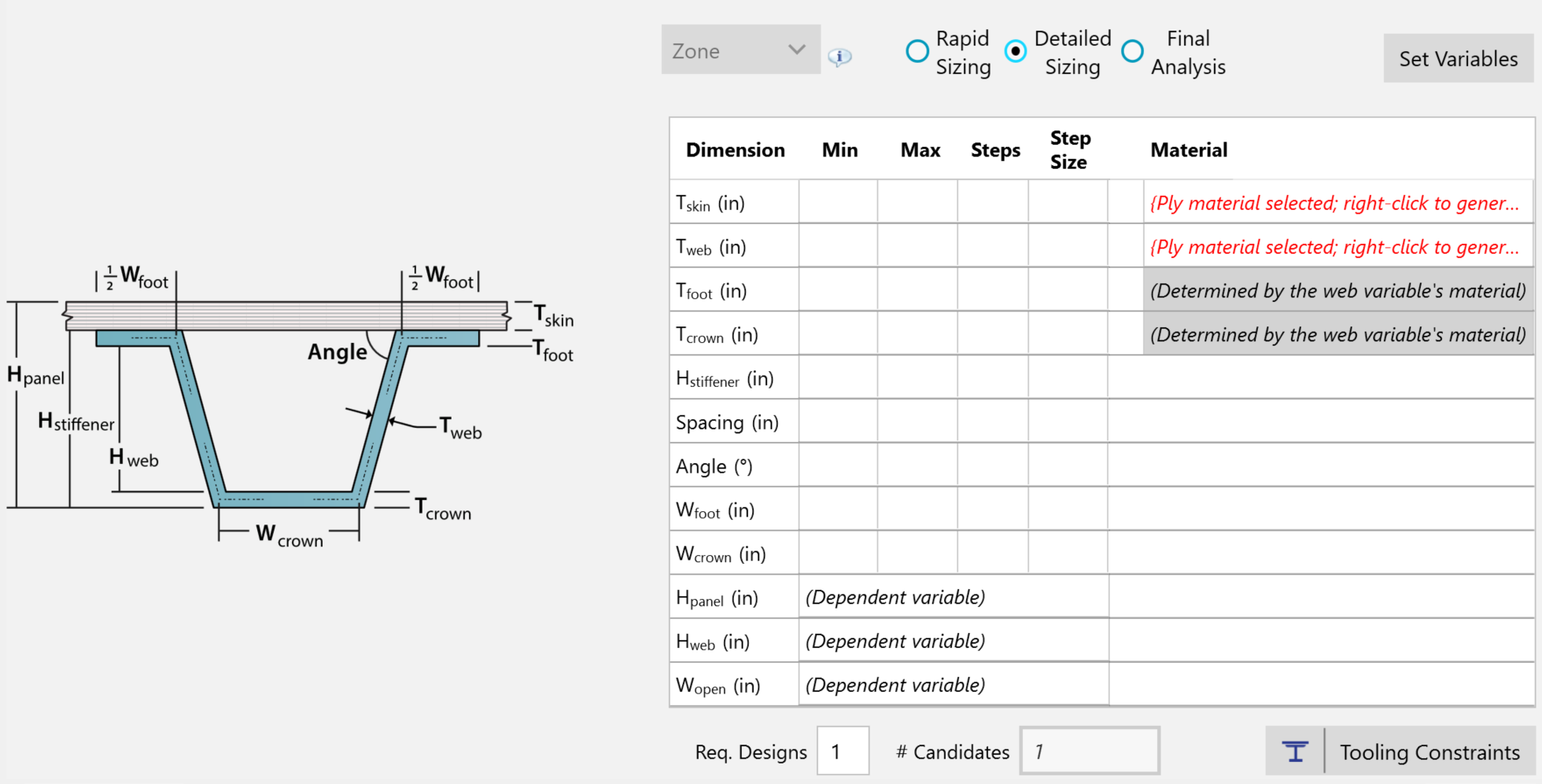
Detailed Sizing mode does require the user to define variable bounds.
The user enters values for each row of the independent variables. Optionally, once rapid sizing is used to funnel down to a focused design space, you can use a ‘Set Variable’ function to automatically generate appropriate min/max bounds and sizing steps for each dimension.
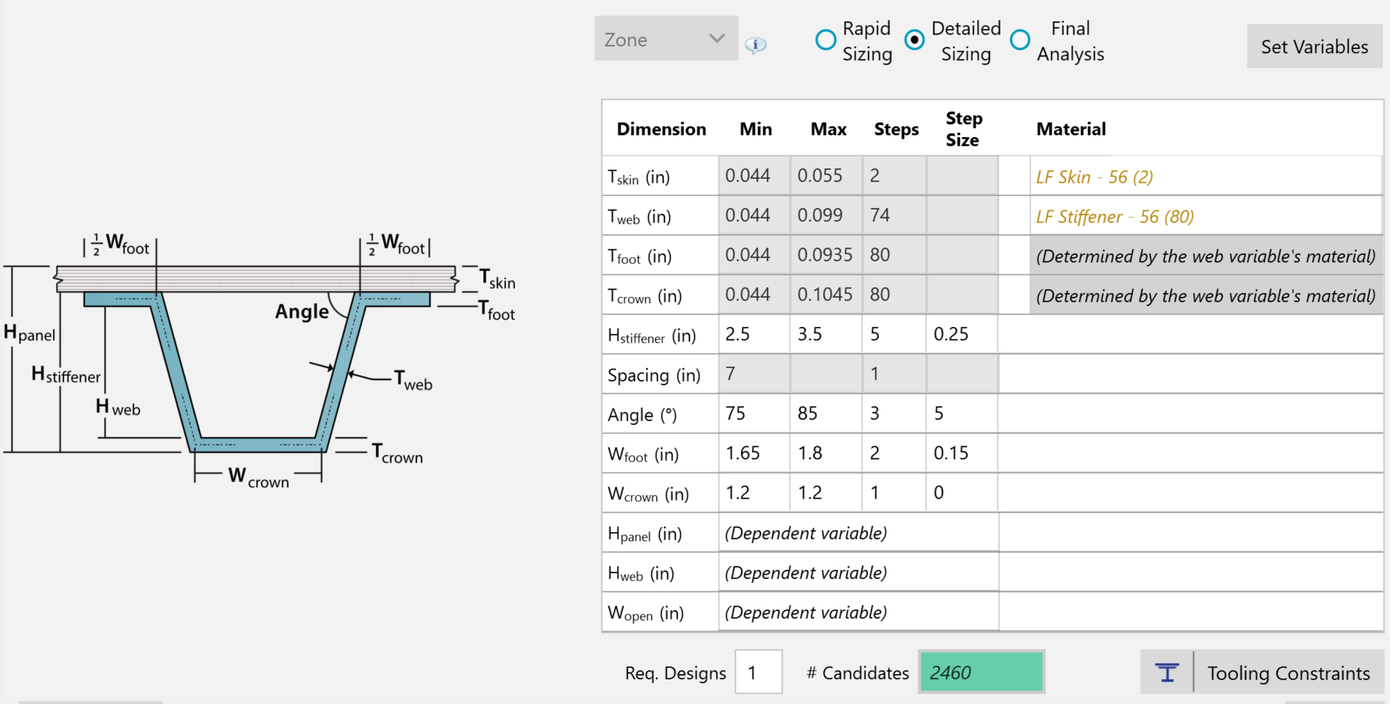
Set Variables automatically defines variable bounds.
The Set Variable function will also generate laminate families containing discrete laminate stacking candidates. Below is an example of a hat/omega stiffener laminate family that was generated that includes foot, web, and crown charges.
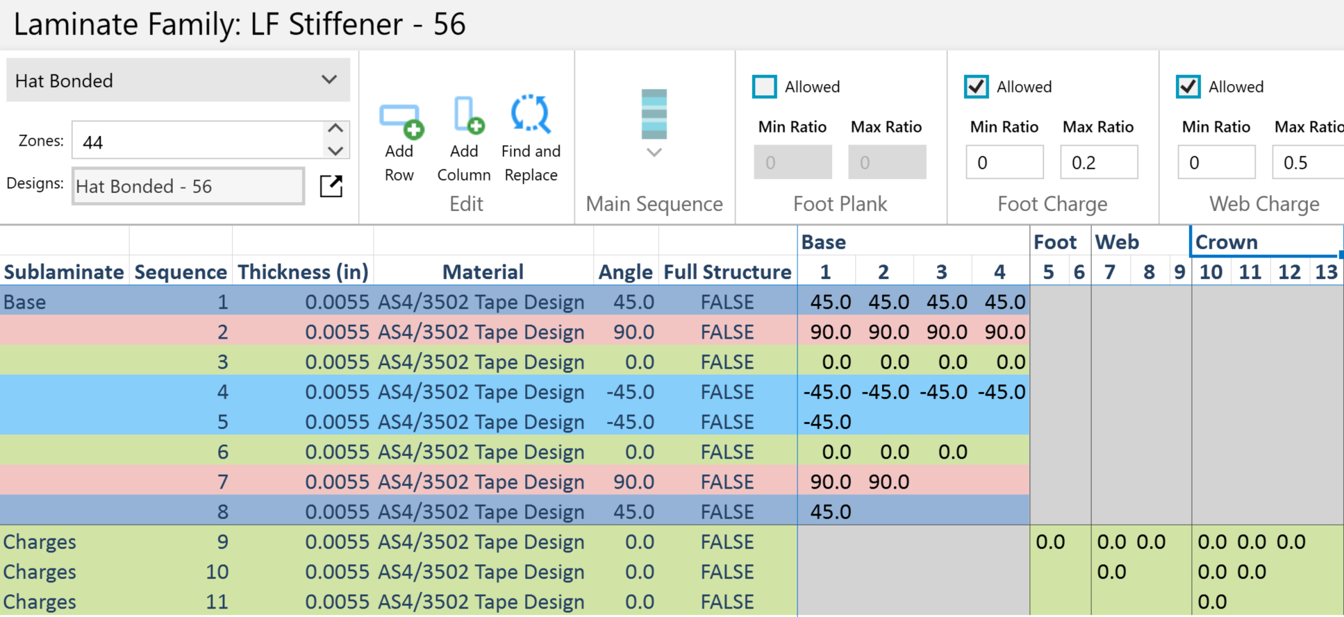
Set Variables automatically generates stiffener laminate families based on ply charge fabrication preferences.
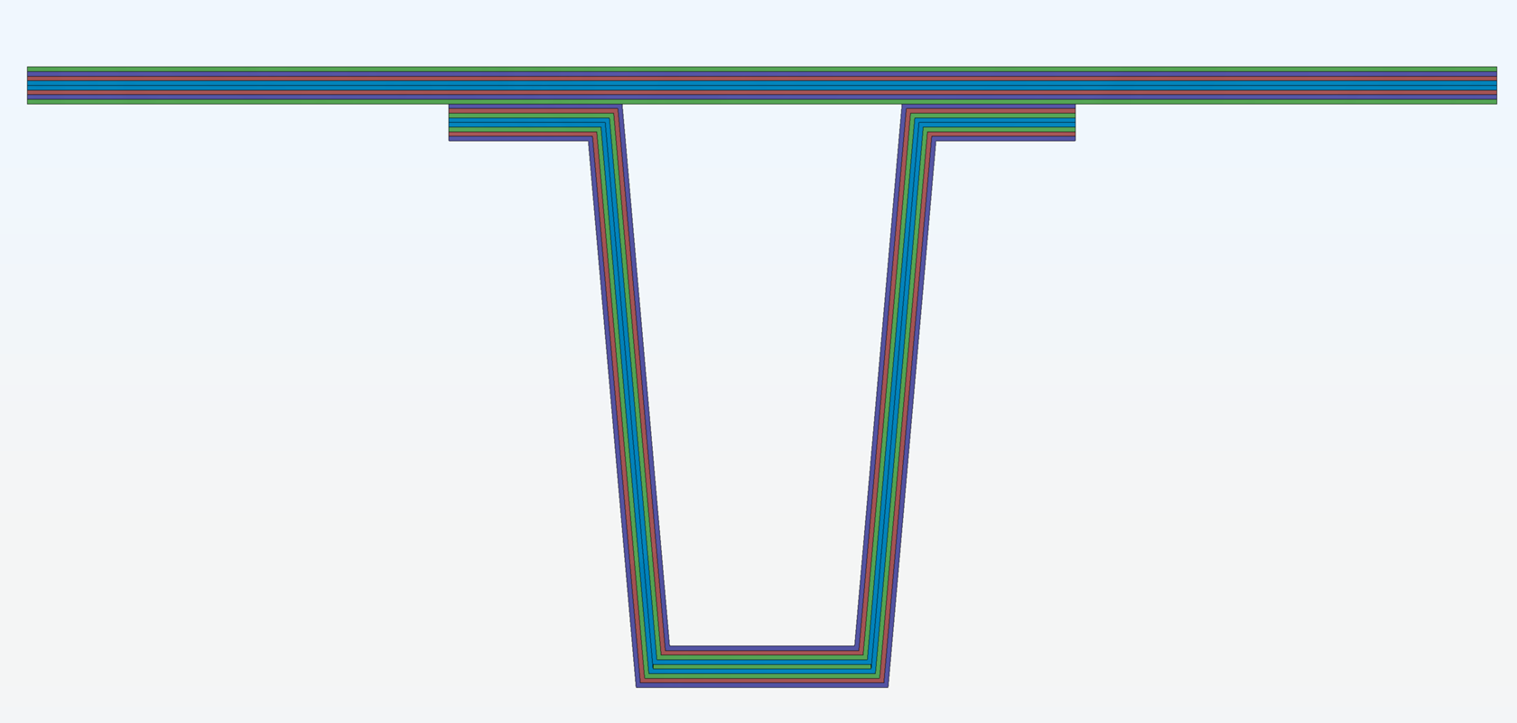
Image generated from detailed sizing. An optimum hat panel shape and skin and stiffener laminates.
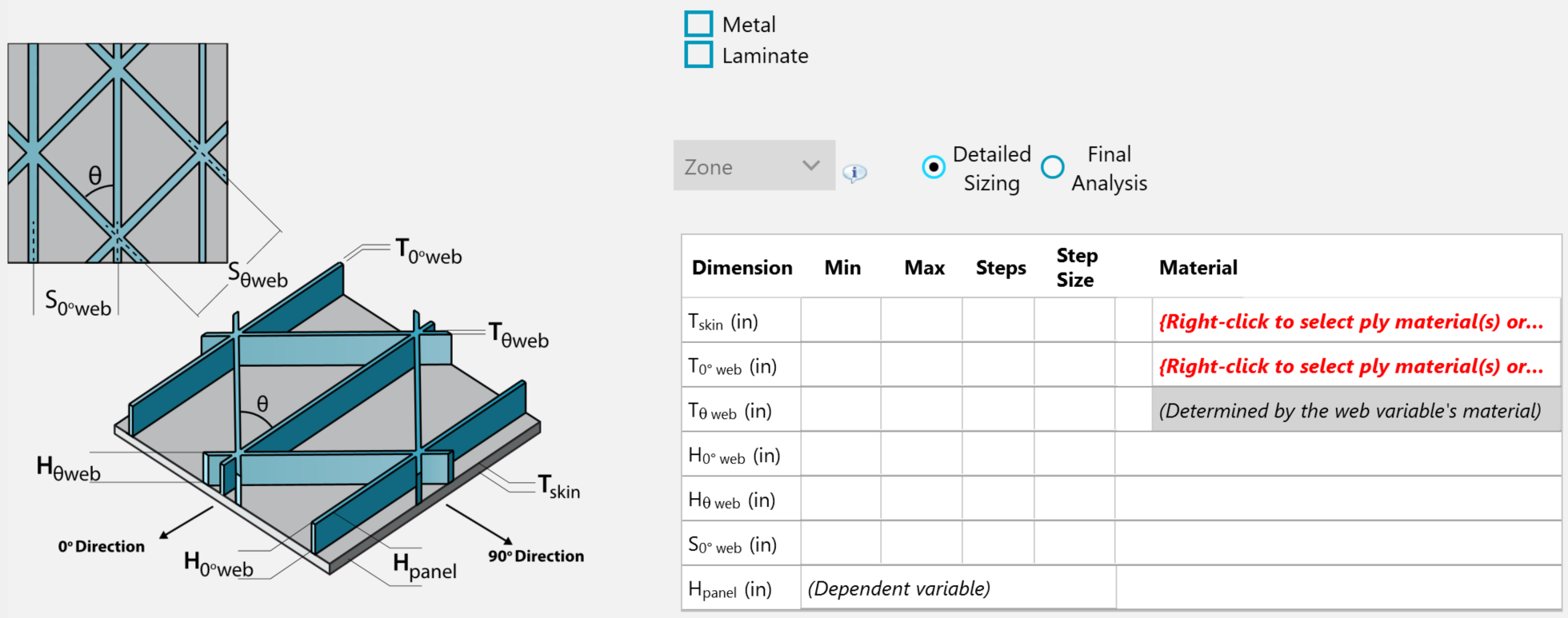
Detailed sizing isogrid panel.
Detail Sizing Joints
In a few minutes rigorously size many structural joints to all load cases. Evaluate different joint concepts. User controls variable bounds.
Benefit
Detailed joint sizing, like panels, is a parametric optimization approach that does require the user to define variable bounds like the minimum/maximum value per dimension. You can specify min and max bounds and the order in which to size variables to achieve positive margins.
Detailed sizing is available for all fastened, riveted, and bonded joint concepts; with any material.
All fastened, riveted, and bonded joint HyperX analyses methods such as bearing and bearing by pass can be used with detailed sizing. The optimization will satisfy all analyses with a positive margin of safety.
In Action
You can prescribe variable bounds based on similar designs from the past, or based on your experience. By inspecting controlling failure modes, you will be able to interpret what bounds to change to achieve positive margins of safety. Sizing is highly interactive and responsive which provides the ability to control the design result.
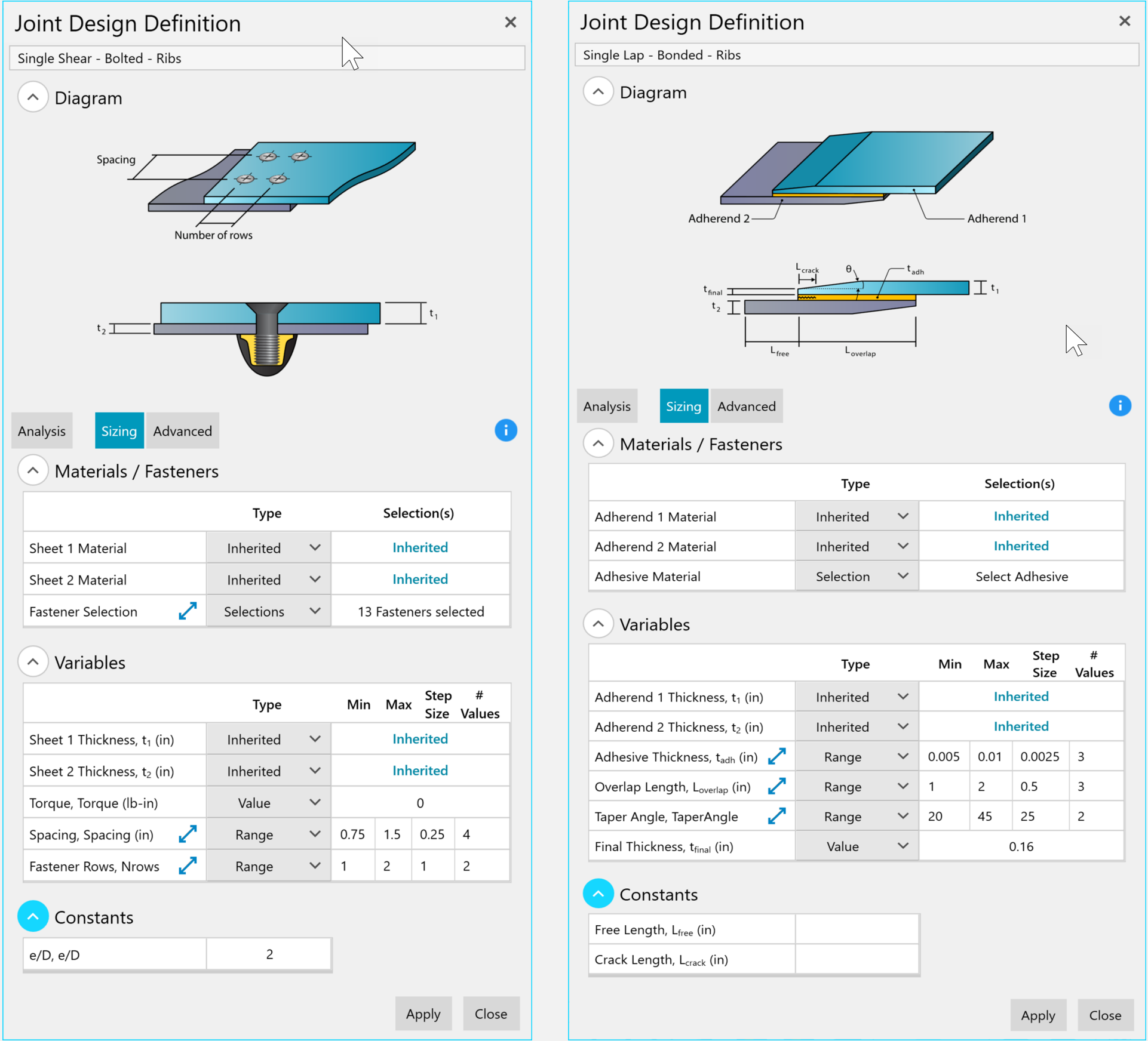
Joint sizing form. Fastened (left), Bonded (right).
Fastened or bonded joint sizing can be performed at any time. If performed before acreage panel sizing, you can specify the material and thickness, or laminate candidates of the connecting structure to consider during optimization.
If joint sizing is performed after acreage panel sizing, you can choose to inherit the material and thickness, or laminate of the connecting structure. In which case the fastener type, diameter, and spacing are sized to attempt to find a positive margin without needing to change the acreage design.
For producibility, the objective is to find consistency across joints. This is achieved with the ‘Advanced’ mode of the sizing which allows the user to select the order in which variables (fastener type, size, spacing, rows) are processed to achieve positive margin. The user can set the fastener spacing to change first, starting out far apart and getting closer (descending), and if that doesn’t work, to try second larger diameter fasteners (ascending), etc.
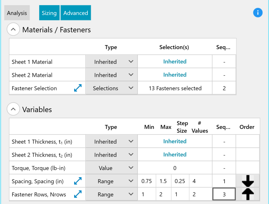
Joint Design form in advanced sizing mode that allows you to select the order in which to size variables to achieve positive margins. Arrow up is ascending order; arrow down is descending.
Interactive Optimization
HyperX’s interactive optimization approach facilitates the user to start with an open design space with millions of candidates and funnel down to a preferred design.
This section introduces the opportunity and challenges of optimizing all variables simultaneously. A honeycomb sandwich panel with composite laminates is the example used to describe the need for you to be able to steer the optimization.

Many material and laminate alternatives to optimize.
Challenge
For this example, there are 3 different honeycomb core materials to consider, and each material has 3 different core densities. If 4 different core thicknesses are being evaluated, the full factorial would be 4*3*3= 36 candidates.
All panel concepts can have many different composite laminate design variations. First is ply material. Some are suited for different manufacture processes, such as autoclave or out of autoclave. Each material can be in a different form, such as unidirectional tape or fabric. In this example the laminate has 2 manufacturing suppliers, 3 ply thicknesses available, 2 material cure processes, and 2 forms; for a total of 2*2*3*2 = 24 ply material candidates.
When it comes to laminates, not only does the design need optimal ply counts in the three primary directions of 0, 45, and 90 degrees, but also a ply-by-ply stacking order. The stacking order and ply counts follow design rules.
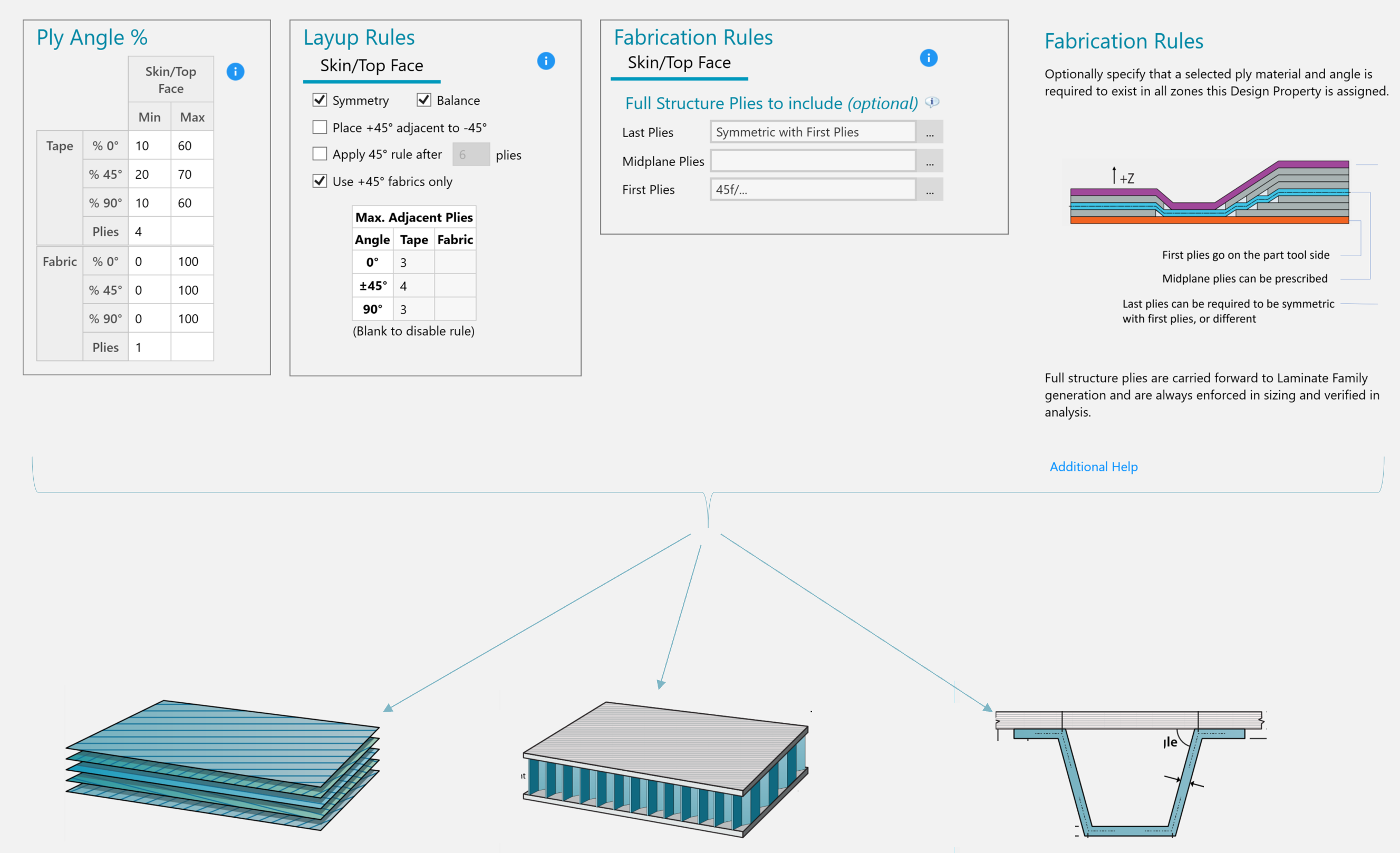
Different laminate design rules can be applied to different panel concepts.
When optimizing laminates, you can quickly establish the weight impact of ply layup rules. Layup rules constrict an open design space and generally increase weight. On the other hand, constricting the design space makes the design more producible and certifiable.
For this example, let’s say conservatively that after you select layup rules to apply based on sizing results, there are about 100 laminate stackings to consider for a sandwich facesheet. The total number of candidates for the composite sandwich then becomes = 100*24*36 = 86,400. Multiply that by the number of structural zones in the model, which being conservative again say is 100. This becomes 8.6 million candidates to process through all load cases. And if the top and bottom facesheets are allowed to size separately, then it becomes 8.6m*100*24= 17 billion candidates to process; through all load cases.
Solution
As you can see, there is a need for you to be able to interact with the software, to steer the direction every step of the way in the design maturation process. HyperX has been designed from the beginning 27 years ago to be interactive with you by giving immediate results feedback to your design data selection or changed analysis method. You have insight into how loads and failure modes are driving your design. From this and with your engineering experience you control what to try next with the software as well as the design decisions to make.
Throughout HyperX’s responsive rapid and detail sizing processes that you control, you are able to funnel down your design decisions.
Contact Us
This site is protected by reCAPTCHA and the Google Privacy Policy and Terms of Service apply.
