FEM Workflow
Import FEM, assign elements to structural zones, extract FEA computed forces, analyze and size each zone, update the FEM, and rerun the FEA solution to compute new load paths.
Capability Pages

eVTOL aircraft– photo credit Joby Aviation.
Introduction
Steps
The HyperX workflow automates a typical process used in the aerospace industry:
- Import FEM
- Convert elements referencing the same FEM property into structural zones
- Extract FEA computed forces per load case
- Analyze and size each zone
- Report controlling load cases, analysis criteria, and critical margins
- Update the FEM with new element properties
- Rerun the FEA solution for new load paths, then reanalyze and size
FEM Import
Import your FEM to analyze and size each FEM property zone. Leverage preprocessor specific data to set up structure entities.
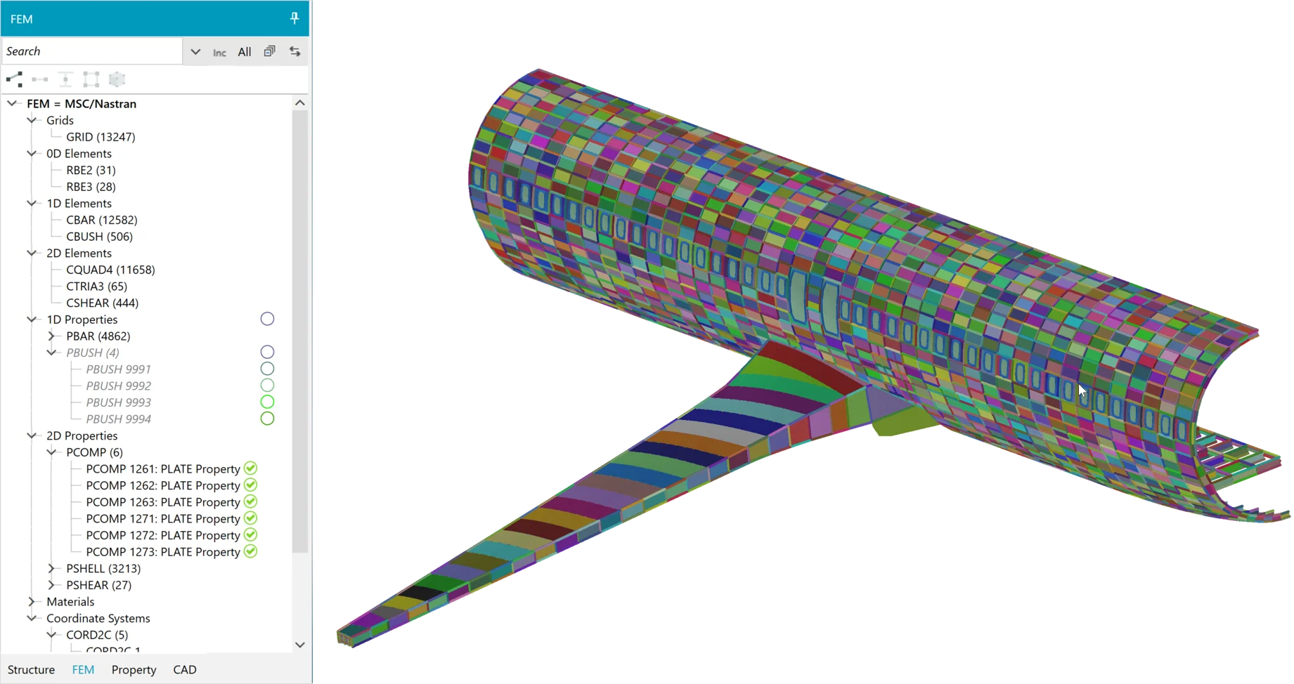
Each color represents a different structural zone as defined by the FEM properties.
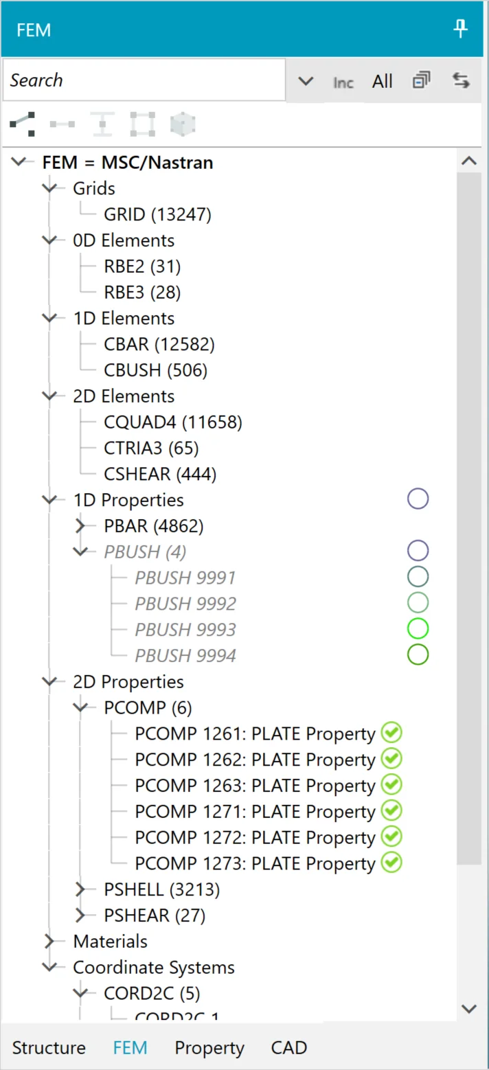
FEM tree with element and property counts in parenthesis. Green check mark indicates FEM properties have been processed into Structure Zones.
Finite element models from Nastran (MSC, NX, Optistuct) and Abaqus are supported.
1D beam, 2D shell, and 3D solid FEM element, property, and material types are supported. HyperX automatically imports beam and shell elements, as well as connector elements (such as Nastran CBUSH or Abaqus CONN3D2).
Property definitions for beams and shells are also read and can be used to automatically create HyperX design properties. For beams, HyperX processes cross-section definitions like the Nastran PBARL and uses the beam dimensions to generate equivalent dimensions automatically. For shells, metal properties (like PSHELL) and composite properties (like Nastran PCOMP/PCOMPG, which define laminates ply-by-ply) can be preserved during import and used to autogenerate laminates in HyperX, including sandwich cores.
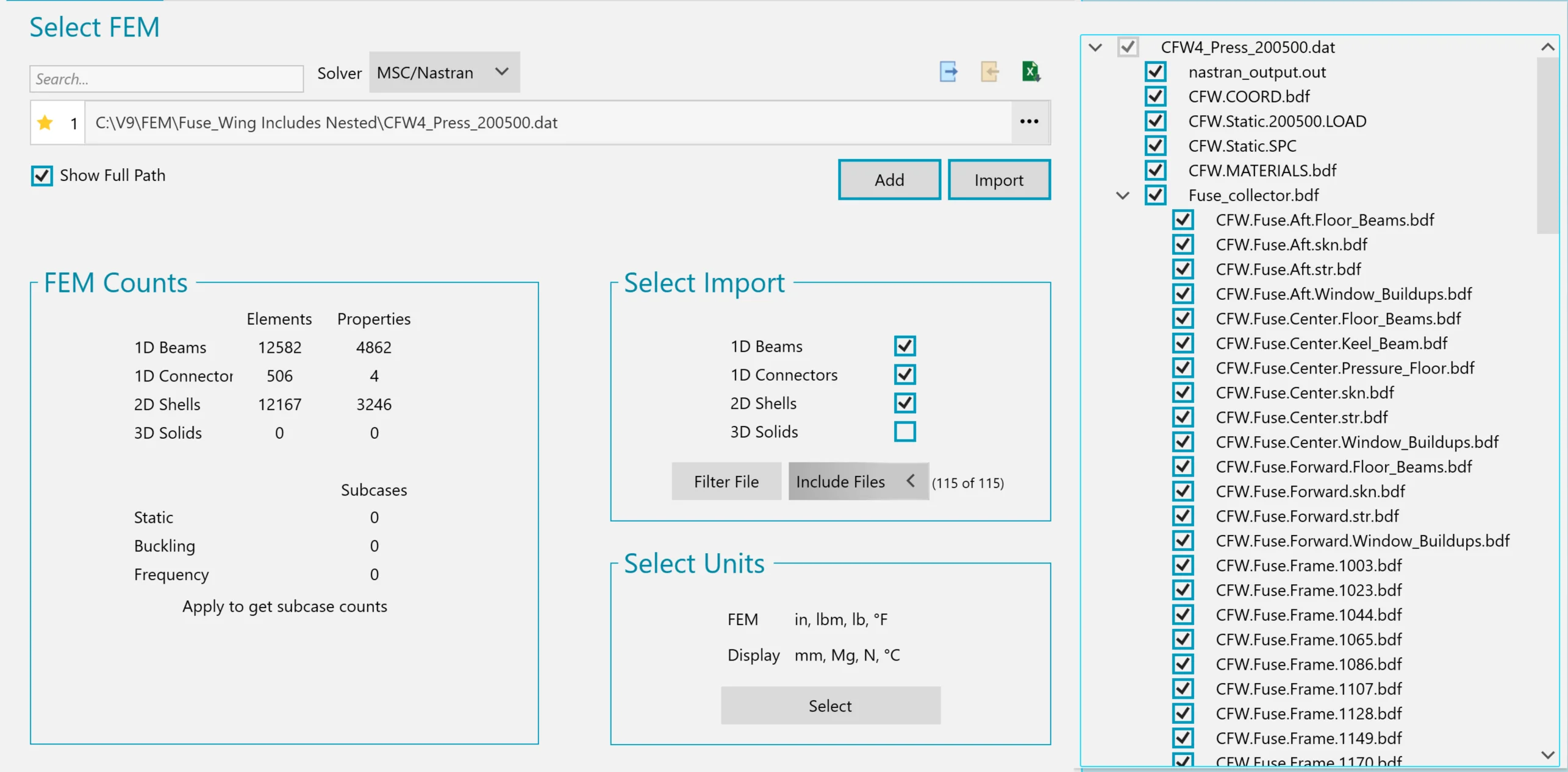
Nested include files are identified (on the right) and can be selected.
HyperX also reads data from the preprocessor such as:
- Include file organization
- Element sets
- Altair HyperMesh parts and assemblies
The user can leverage this information when setting up their project. For example, HyperMesh assemblies or include files can be converted into individual structures. This enables integration between two different engineering teams and makes the design iteration process quicker. Example: the FEM creator makes HyperMesh assemblies which are processed by HyperX for you to very quickly, without much setup time, leveraging existing data organization.
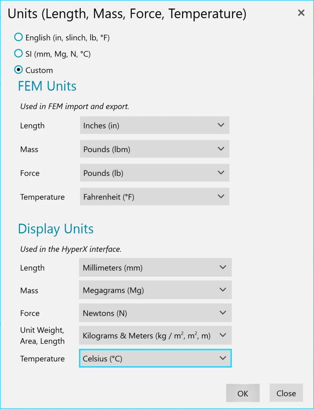
User can select to display model in a different unit system than the FEM.
During import, HyperX calculates span lengths in the axial (X) and transverse (Y) directions, as well as the surface curvature for each FEM property zone. These values are used primarily for buckling analysis.
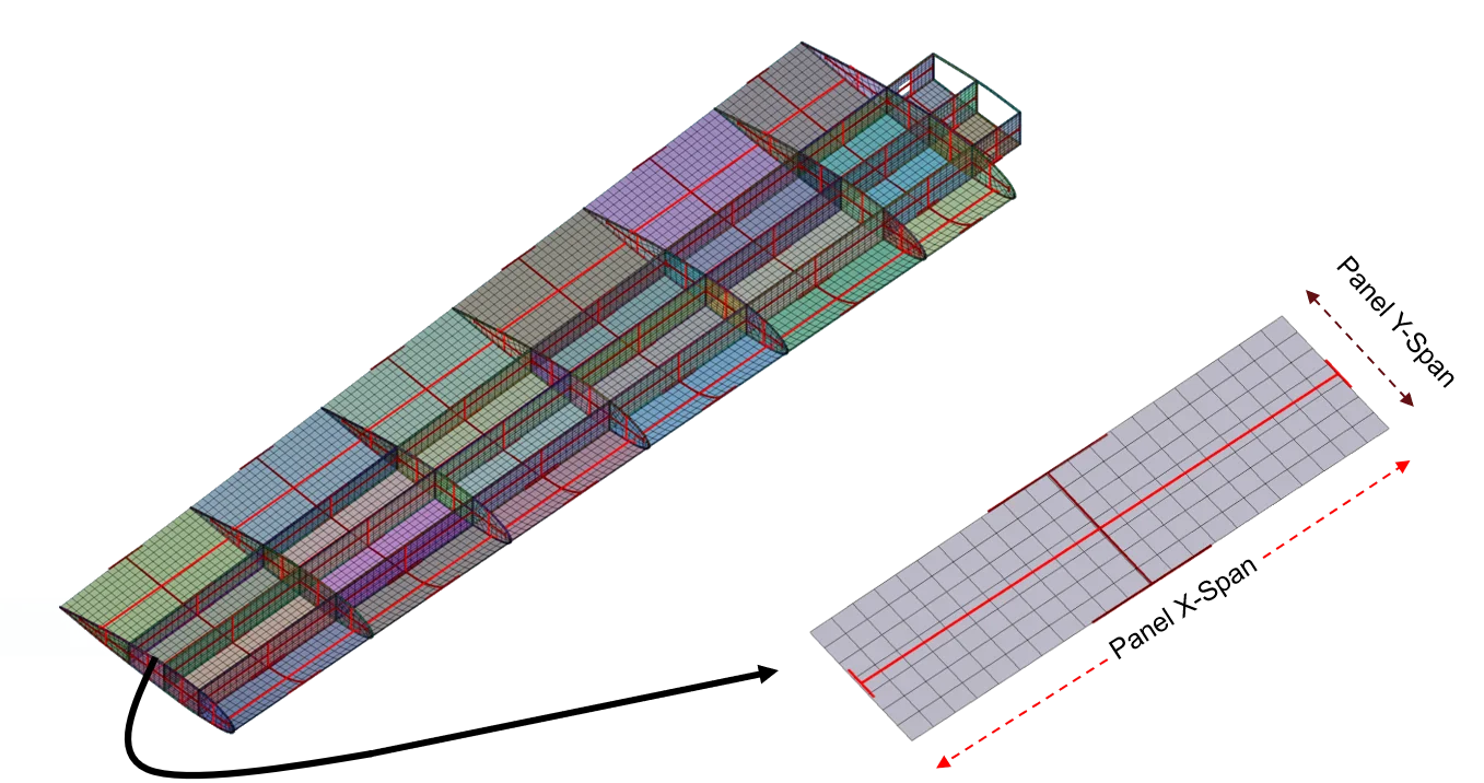
Red markers indicate each zone’s X and Y panel buckling span lengths.
FEA Loads Import
Extract FEA computed element forces per load case. Process large solution output data sets very efficiently to define factored design-to loads for analysis and sizing.
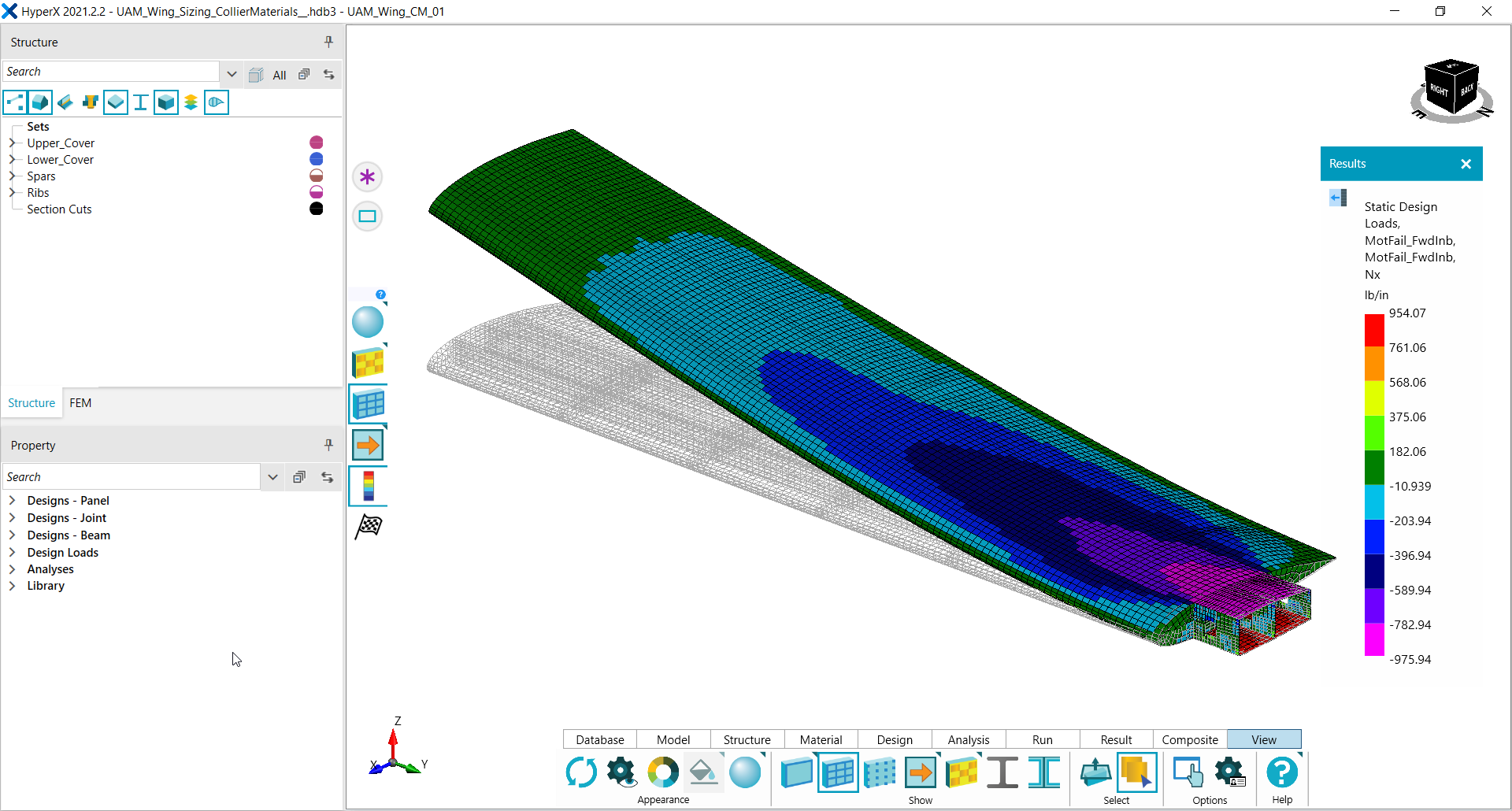
FEA computed results for all supported solvers can be extracted from their output files. For Nastran and Optistruct, the binary OP2 and Ascii F06 formats are supported; for Abaqus, the ODB is used. File sizes of hundreds of gigabytes with thousands of load cases are commonly processed by customers.
Each of the element types supported during FEM import are also supported for load extraction from these files.
Linear static loads are often used to represent the fundamental global FEM behavior. They are used to size for strength and stability of the panels and beams using analytical methods.
FEA solutions for linear and nonlinear static, as well as linear (eigenvalue) buckling and frequency analysis are supported. Buckling eigenvalues are processed to complement analytical buckling solutions. The regions of the model where mode shapes occur below a minimum eigenvalue are automatically tracked and resolved.
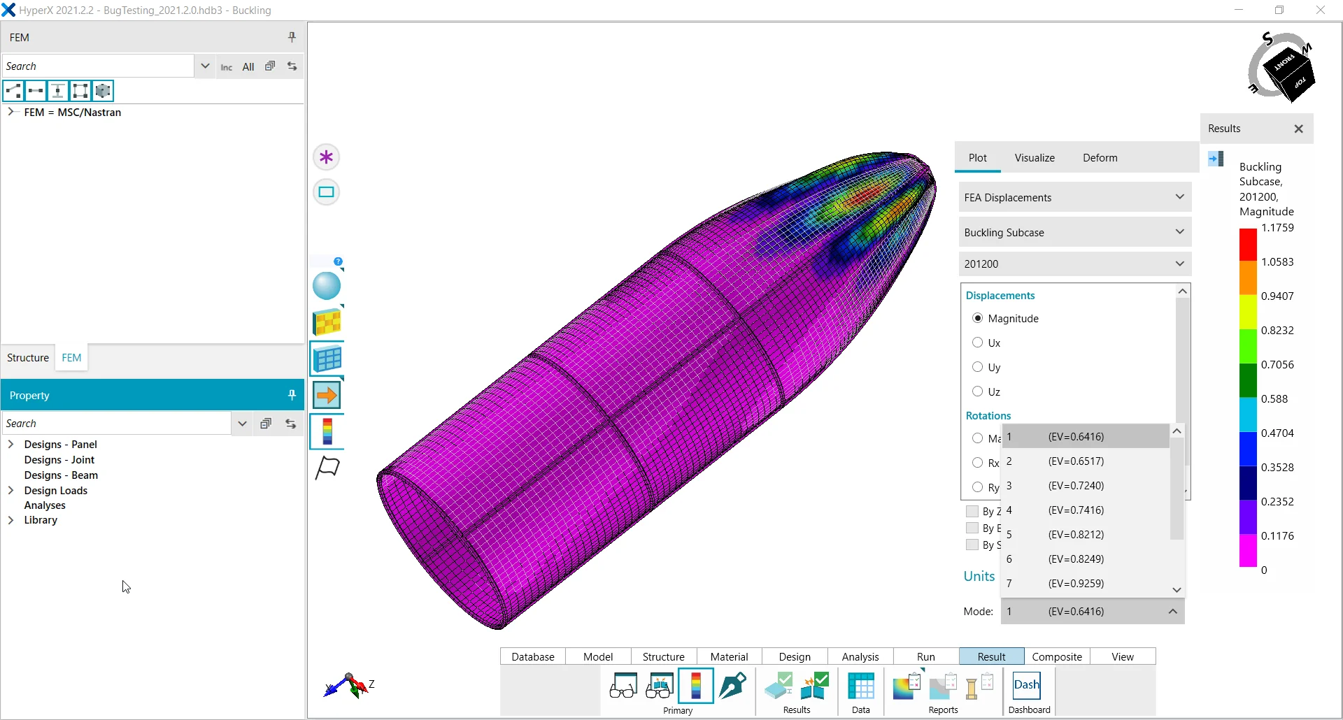
Deflection limits can be set with linear and nonlinear solutions and the structure will be optimized efficiently to meet targets. See feature topic FEA Loads Cycling.
FEA Design Loads
Design loads are created from FEA subcases. A typical design load setup is shown in the image. FEA unfactored load cases are multiplied by factors to establish design-to loads for analysis and sizing. In this case a 1.5 ultimate load factor is used. HyperX will perform analysis and sizing to the 1.0 limit load for appropriate methods such as material yield, and the 1.5 factor for other failure analyses such as the ultimate stress allowable.
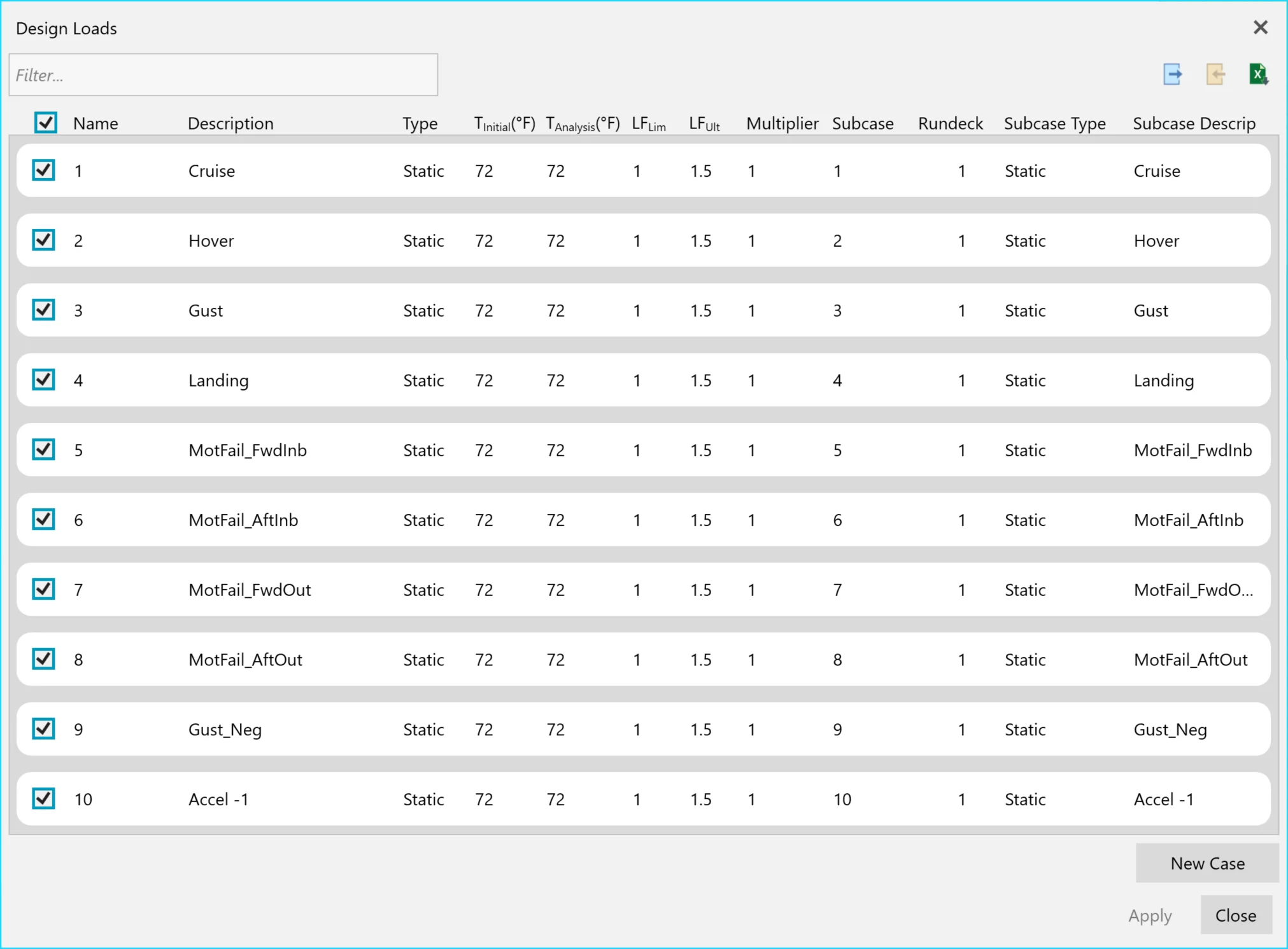
Management of FEA load cases and definition of design loads.
From this form you can create new design loads by superimposing other load cases. You can also export/import from Excel spreadsheets, which can be useful when managing thousands of design loads.
Design loads allow the user to create and manage the actual conditions that are used to size and analyze a structure. The user selects one or more FEA subcases which are then linearly superimposed. Common applications include flight cases with and without fuselage pressure, or cases which consider thermally-induced stresses. By managing the combinations in HyperX, the total number of FEA subcases (and FEA runtime) can be reduced.
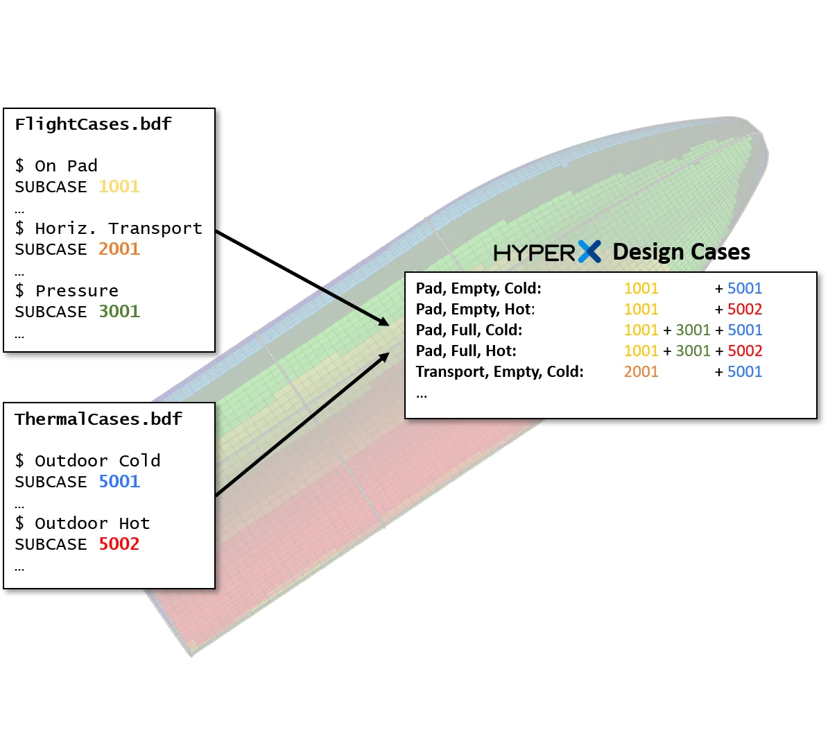
The Design Loads form allows you to assign an analysis temperature per design load. You can also identify a load case as being a thermal or fatigue load case, each with their own load factors.
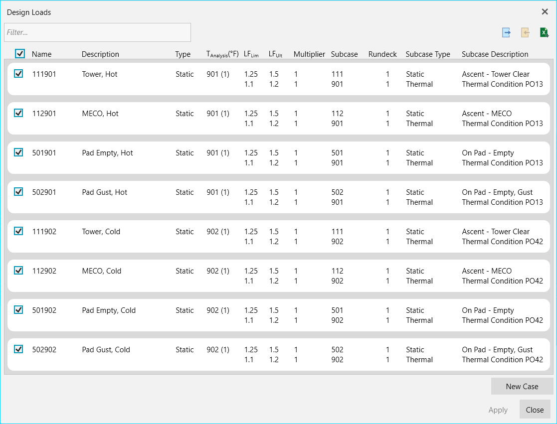
The temperature used for retrieving material properties impacts the analysis. Correctly tracking the appropriate temperature for each zone and design case with HyperX simplifies this complex and time-consuming task. Analysis temperatures can either be given a single blanket value model-wide, or they can be extracted from a subcase. Applied FEA temperatures are then used to determine analysis temperatures on a case-by-case and zone-by-zone basis.
See feature topic Load Property to learn about HyperX methods for processing element loads, per zone, into average, statistical distribution, or peak values.
FEM Update
After optimizing the model zones, HyperX automatically updates FEM properties with new shell thicknesses, laminates, and beam properties.
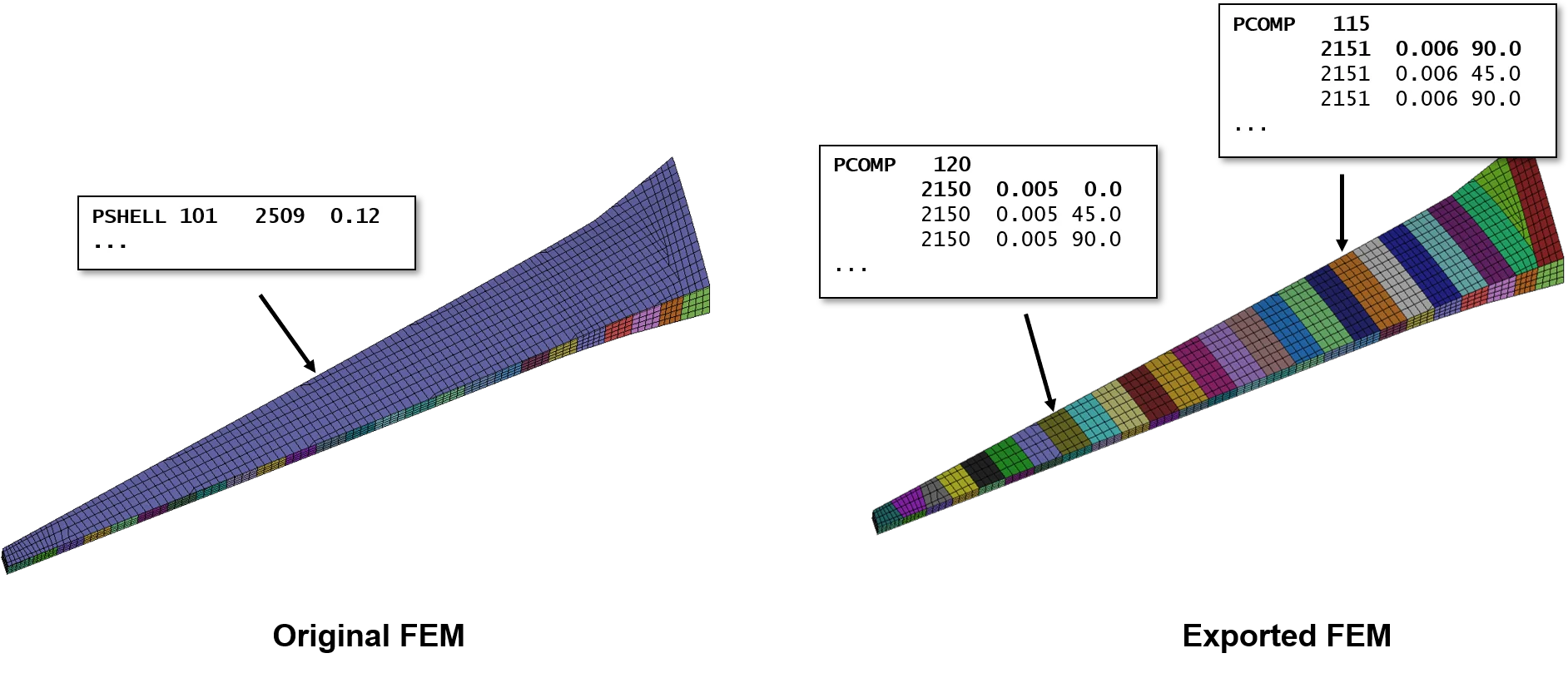
Primary updated data are properties, such as Nastran PSHELL or PCOMP types. In order to update shell and beam offsets, their corresponding property types are also updated.
Each of the property and element types supported during FEM import are also supported for model update.
All panel, beam, and joint sizes and materials update the model.
The updated FEM properties are placed into the originating Include files. In fact, the original source FEM file format stays intact. Only elements and properties affected by HyperX sizing are modified and the remaining FEM structure is unchanged. This maintains the user’s familiarity with their files.
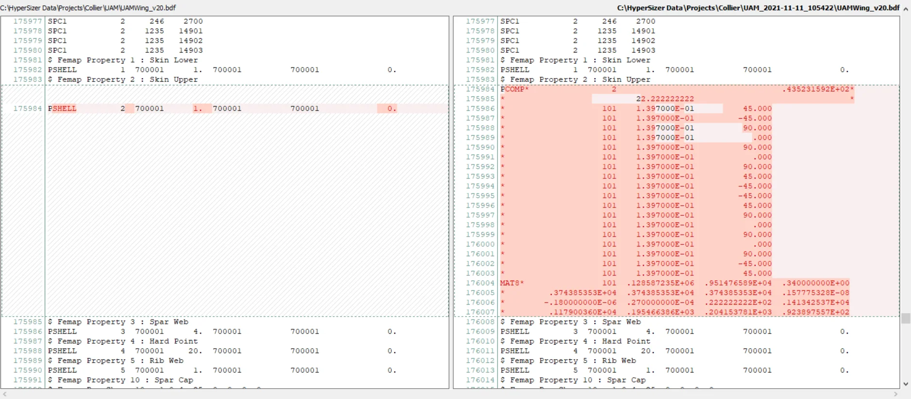
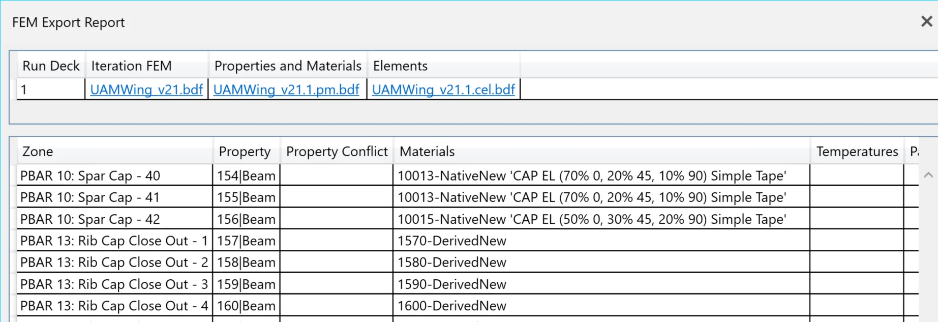
Report identifying the status of each FEM property update.
FEA Loads Cycling
HyperFEA™ automatically iterates FEA solutions and HyperX sizing. Converge load paths and enforce global deflection, buckling, or frequency requirements.
With updated FEM properties, execute FEA runs to get new internal loads. HyperFEA™ is a tool that automatically submits, monitors, and iterates FEA solutions until load path convergence.
It can be used with linear static, nonlinear, or eigenvalue solutions. HyperFEA is most commonly used to iterate a global FEM after optimizing structural zones with updated FEM properties.
In addition to static load convergence, HyperFEA can enforce global model constraints. For example, deflection limits (such as the tip of a wing) can be included and HyperFEA will determine which regions should have stiffness increased to most efficiently meet the requirement.
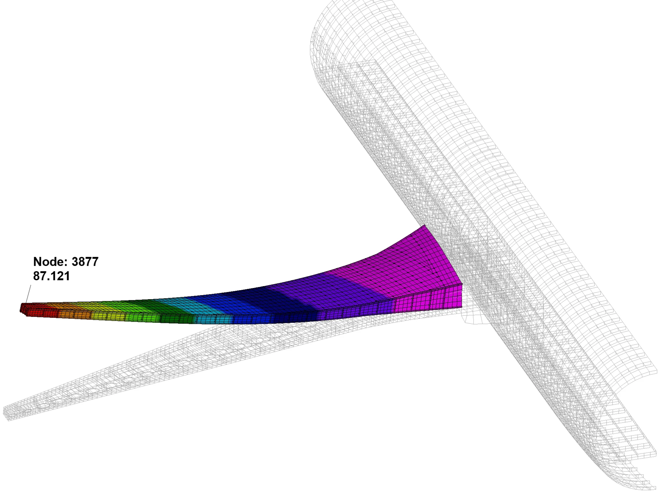
A typical FEA constraint is to assign a displacement limit to a grid or set of grids.
Buckling and frequency eigenvalue analyses are frequently used to complement to analytical solutions.
Although HyperX can accurately predict and prevent buckling of individual panels, FEA is used to predict global modes where more than one zone participates. HyperFEA uses the results of the eigenvalue solution to efficiently drive out modes below the user-provided threshold. Locations where eigenvalue mode occur are identified and each is tracked. Stiffness is increased in regions of the model that are buckling below the requirement, simultaneously for as many modes and subcases as the user has provided.
The example below shows modes on an aircraft rib that are large and include the rib stiffeners (posts) as well as the skin pockets. An eigenvalue increase from 0.2 to 1.0 is achieved with only a mass increase from 252 lbs to 279 lbs.
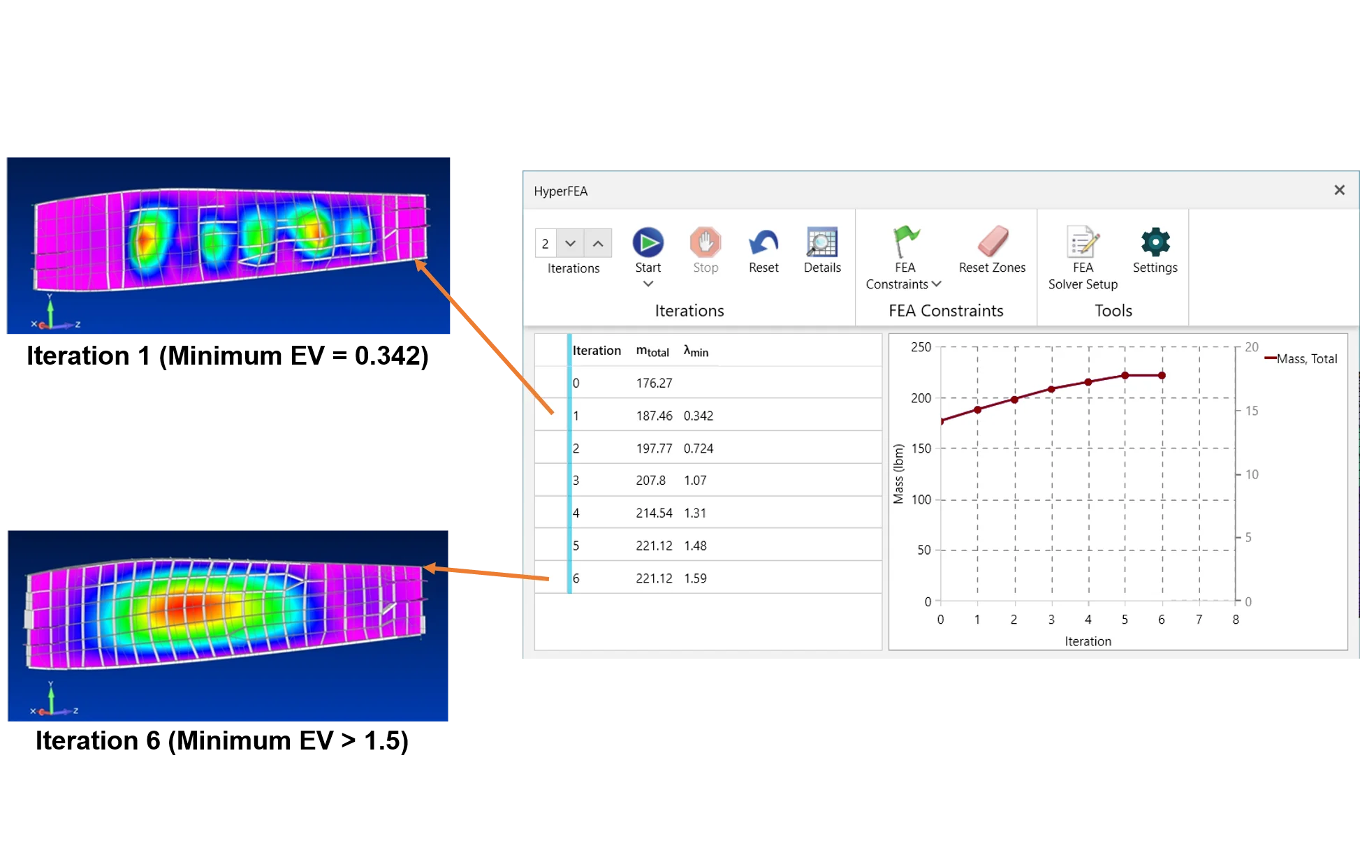
Areas on an aircraft rib model where mode shapes are automatically tracked and resolved.
FEM Reimport
As the design matures, the initial FEM geometry, architectural layout, and/or mesh will be redefined. The new model can be reimported into the HyperX project keeping its previous setup data intact.
FEM reimport reduces schedule by limiting the amount of rework an engineer has to perform to stay current with modeling changes. HyperX maintains the project data setup and identifies detected changes to the FEM for the user. Doing so makes FEM modifications transparent to the user.
The FEM Reimport offers two ‘FEM Mapping Type’ options for user control over the changes to HyperX setup caused by the new FEM changes.
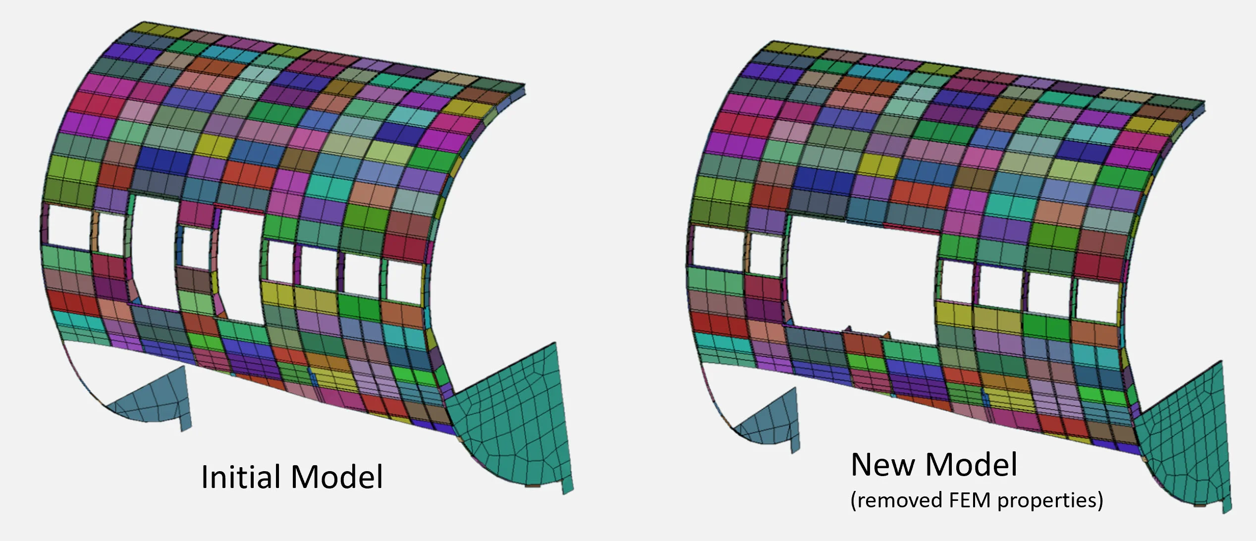
Element Mapping
Element Mapping is used for element definition updates, changes in grid/node positions, and when FEM property zones are removed – as shown in the fuselage door example below.
Property Mapping
Property Mapping is used for FEMs where element/grid numbering has changed, such as caused by remeshing, but property definitions for these regions remains the same – as shown in the wing rib example below.

To maintain the project data setup, the changes to the FEM are identified for the HyperX user (as shown in the image below). Doing so provides knowledge of the FEM differences and areas of the FEM that remain unchanged.
FEM Panel Modeling Techniques
Flexible modeling approaches are supported. Smeared models do not require stiffeners to be modeled, while discrete modeling techniques include stiffeners explicitly defined with beams and shells.
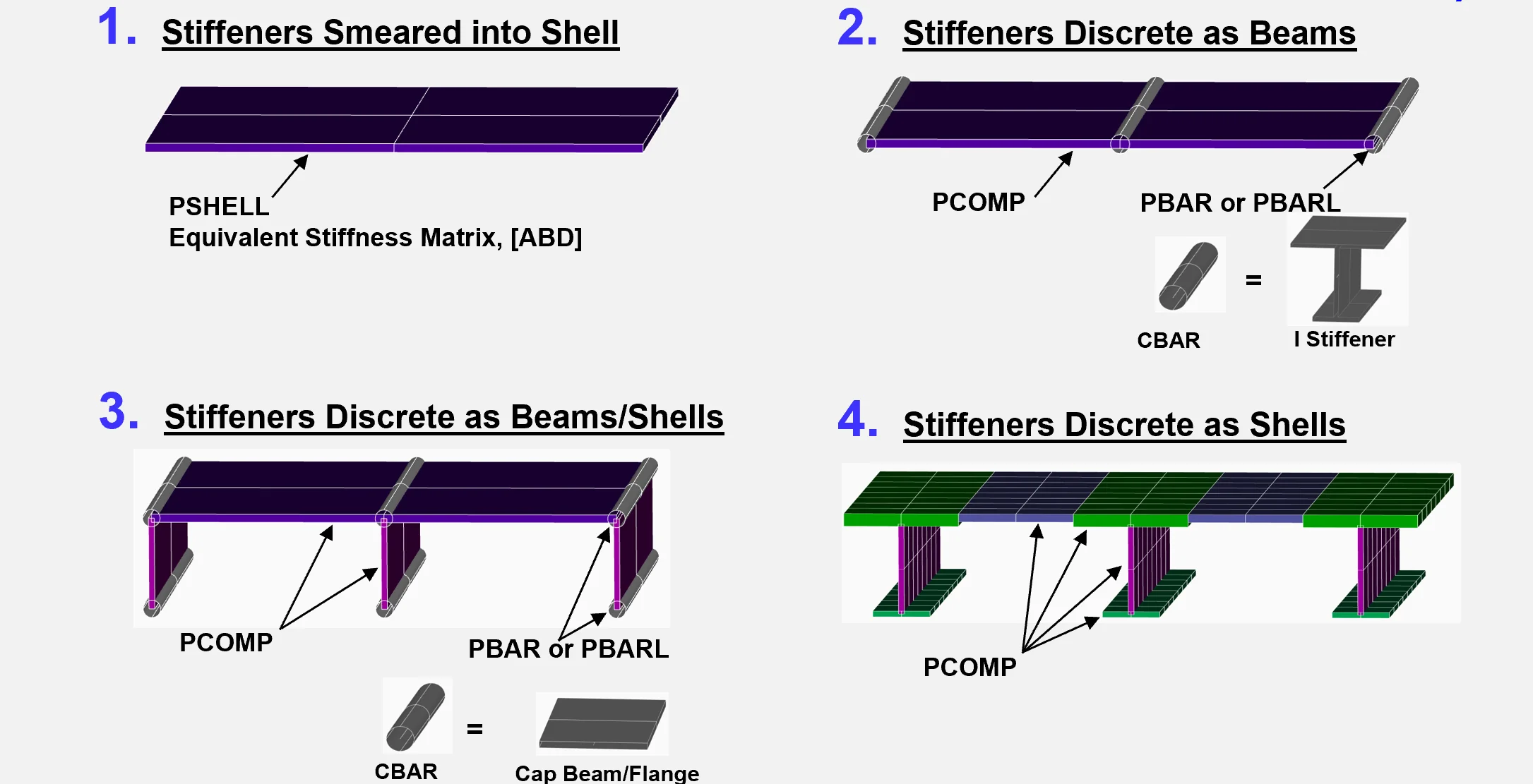
As a project progresses through conceptual design, to PDR, CDR, and certification, the level of detail in the FEM increases. HyperX supports a variety of modeling approaches in order to reduce schedule from start to finish. In preliminary design, the smeared modeling approach provides accurate results with simple models. As the design is finalized, HyperX imports discretely-modeled stiffeners to size and produce margins of safety for every stringer and skin bay.
Time is saved by being able to preserve and continue to use the HyperX project setup data when transitioning from one modeling technique to another.
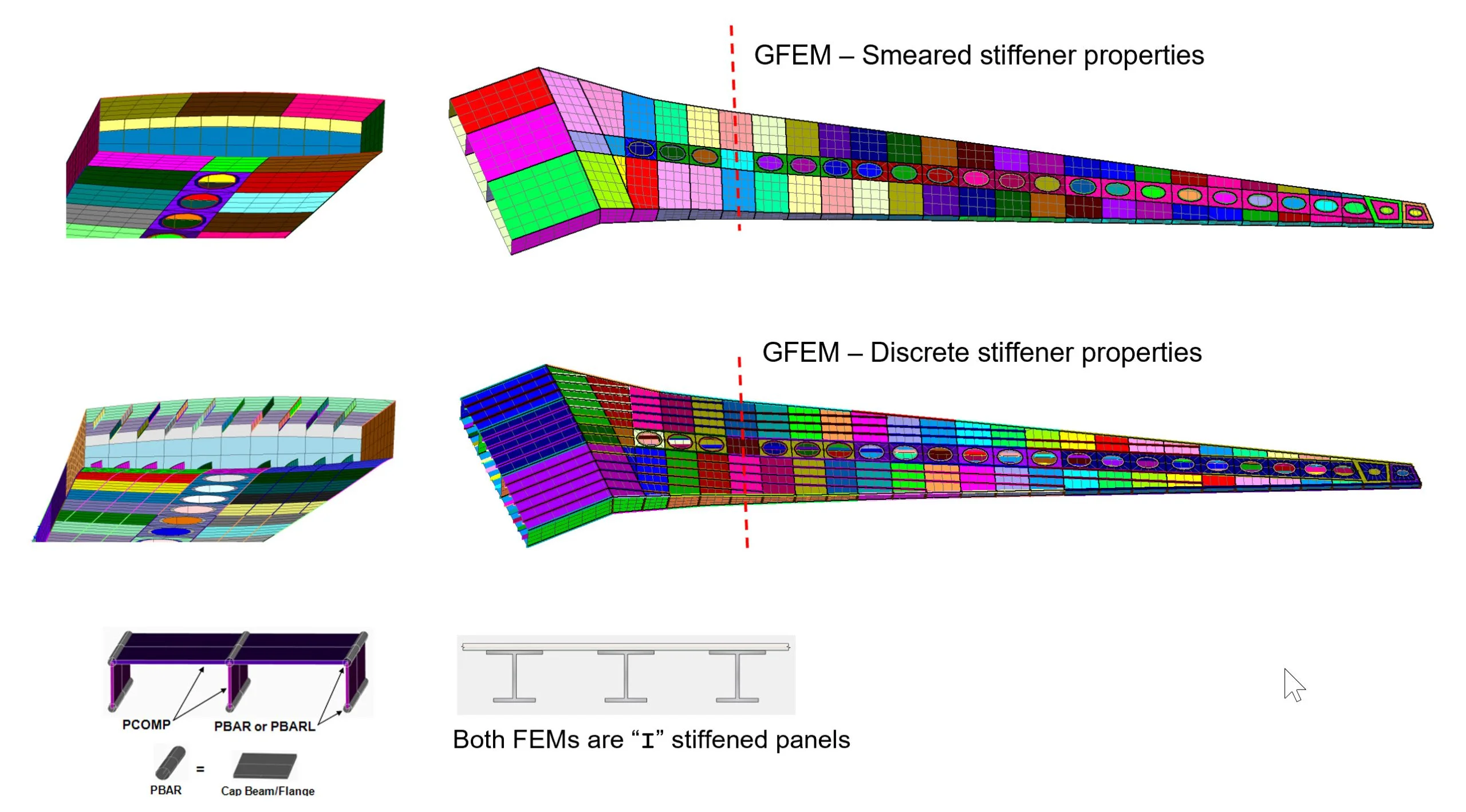
The standard industry practice is to use two types of finite element models (FEMs) in the design of metal and composite wing and fuselages and their associated stringer/stiffener, spar, rib, and skin components. The process generally begins with a smeared model in the preliminary design phase, during which all sizing variables are optimized concurrently. Having decided on stiffener location – and ‘frozen’ tooling specifications – analysts may then transition their 2D smeared models to 3D discrete stiffener models (DSM). In this stage, engineering teams typically perform detailed structural analyses with HyperX for all panel segments. As the design progresses, other cross-sectional dimensions are locked down, too. Laminate specifications are finalized, and margins of safety calculated, with failure analyses stress reports automatically generated by the software for all parts required for flight certification.
During this process the software provides additional automation of workflows. All material, loading, and sizing data can be automatically transferred intact from a smeared to the discrete stiffener model, with stringers represented individually by beam or shell elements, or a combination of the two. Engineers can then identify each stiffener as a separate panel segment, select failure analyses, and determine unique margins of safety for each. With this added flexibility, they can create panel bays with stringers of varying dimensions and materials, and capture the strength and weight benefits of non-uniform spacing and termination. Other advantages include interpreting how the stringers and skins fit together to form a stiffened panel, calculating stiffener spacing and heights automatically, and mapping the loads for crippling and buckling analyses.
FEM Smeared Models
HyperX’s unique thermoelastic panel formulation allows a 2D planar shell mesh to accurately represent the membrane-bending stiffness of many panel shapes.
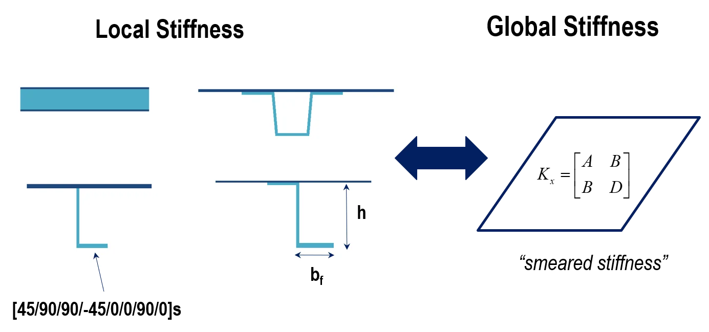
For stiffened panels, HyperX has a powerful and unique capability to represent membrane-bending and coupling stiffness of open and closed cross sectional shapes with 2D planar shell elements. The benefit is that different stiffened panel concepts such as hat/omega, Tee, Blade, and Zee can accurately be analyzed without having to remesh the model to capture their shapes and stringer spacing.
Smeared models allow the user to efficiently trade stiffener spacing, materials, and even stiffening concepts to find the optimal configuration. Engineers might trade honeycomb sandwiches, composite Z stiffeners, and machined orthogrid all with the same FEM using this smeared approach.
This is accomplished by fully computing Aij, Bij, Dij stiffness terms. In the case of Nastran, this is implemented with a MAT2 and four PSHELL data types. For Abaqus, it is implemented with the General Shell. Several technical papers are published and available. Technical Papers
FEM Discrete Stiffener Models
The discrete-stiffener modeling (DSM) approach explicitly models stiffeners with bars, shells, or a combination of element types.
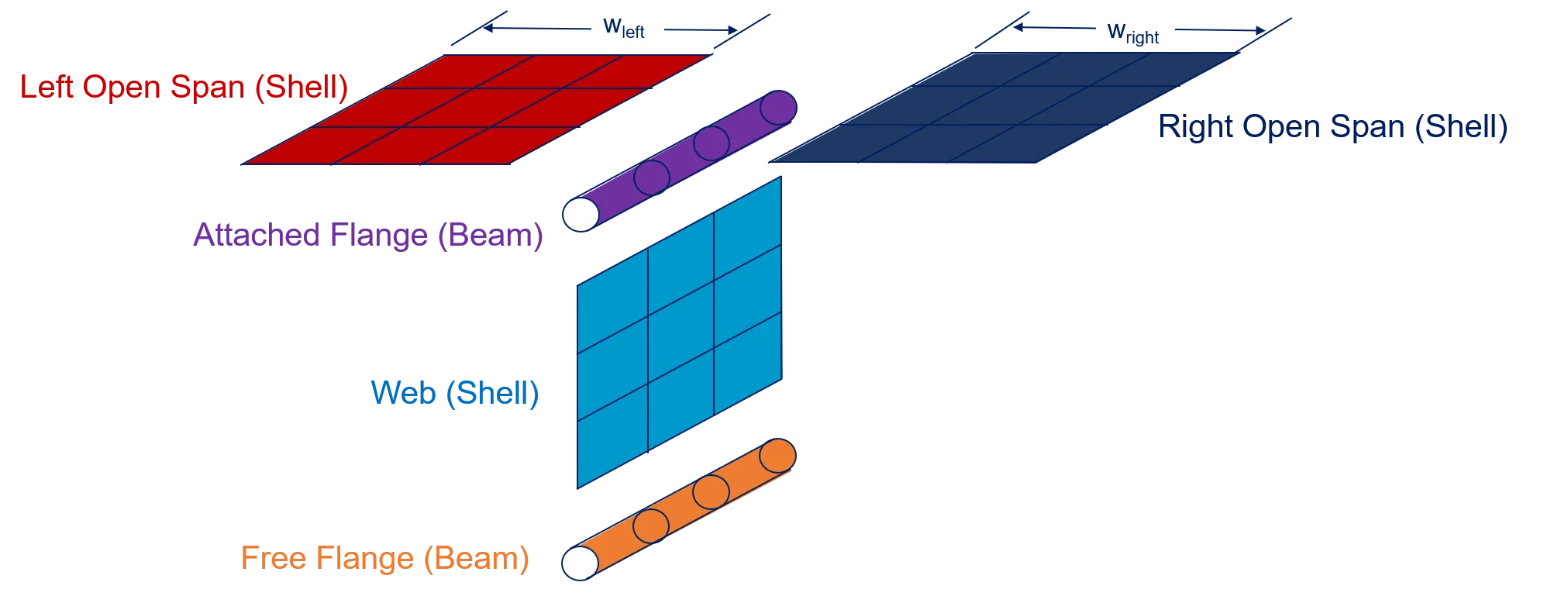
The discrete-stiffener modeling (DSM) approach is commonly used as a project progresses past PDR. Explicitly modeling stiffeners allows FEA load extraction of the skin separately from stiffeners.
HyperX automatically detects and associates the skins attached to each stiffener. The assembled sectional forces are “built up” using the skins and stiffener elements and localized to each object in the cross-section. This accurately redistributes the forces in the section as it is sized; for example, if the stiffness of the free flange is reduced, HyperX accurately determines how the load is distributed in the rest of the cross-section, without having to rerun FEA.
Contact Us
This site is protected by reCAPTCHA and the Google Privacy Policy and Terms of Service apply.
