Plies
HyperX optimizes plies to minimize weight while maintaining producibility. This is achieved through extensive capabilities to generate, visualize, and edit plies.
Capability Pages


Introduction
HyperSizer was used to optimize the entire rocket fairing structure for “ply compatibility.” The software determined not only the best design but the most practical layup by minimizing drop-offs on the tool, making it much easier to manufacture the part. The software also prioritizes ply drop-off order, avoiding “stair step” drops that can greatly diminish laminate performance. “Well over a million candidate layup arrangements across each panel surface were evaluated so that the lightest design was also the most manufacturable.”
Composites World – Optimizing the Ares V Payload Shroud – Hyper X (collieraerospace.com)

Ply Sequencing
The minimum-weight laminate for a zone is not always the most producible. Ply sequencing assembles zone laminates into producible plies on a structure.
Sequencing is used to assemble laminates that were optimized for individual zones into plies that cover a structure. A tradeoff exists between weight and producibility in the sequencing process. The minimum-weight solution allows a lot of variation from zone to zone. This can result in a lot of “island” plies because the laminates are highly tuned to each zone. At the opposite end of the spectrum, having the same plies covering all zones would be highly producible, but heavy. The sequencing process seeks a compromise by exchanging laminates for heavier but more producible options to fill in gaps and connect “island” plies. The user can dictate the sequencing emphasis on weight vs producibility.


Ply Scoring
Producibility of plies is assessed by considering two primary features: ratio of perimeter length to ply area, and orientation of fibers relative to ply boundaries.
HyperX provides producibility scoring for plies during sequencing and within laminate design study tools.
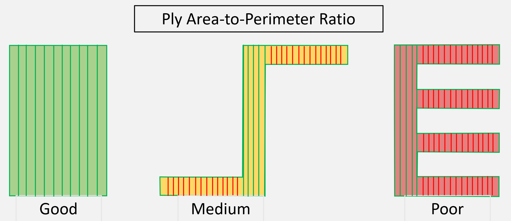
The first metric considered in this score is the ratio of perimeter length to ply area. Shapes such as squares or circles have the lowest (best) scores. Ply shapes that are short and wide have high (bad) scores. Ply shapes with good scores are easier to handle in a hand layup and easier to program in an ATL or AFP layup.

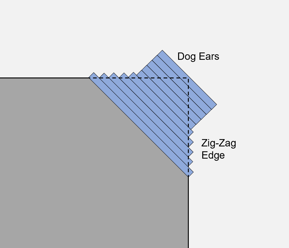
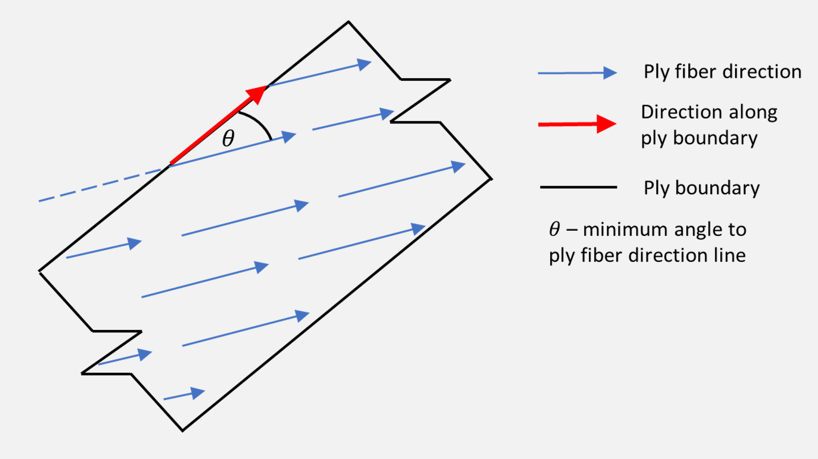
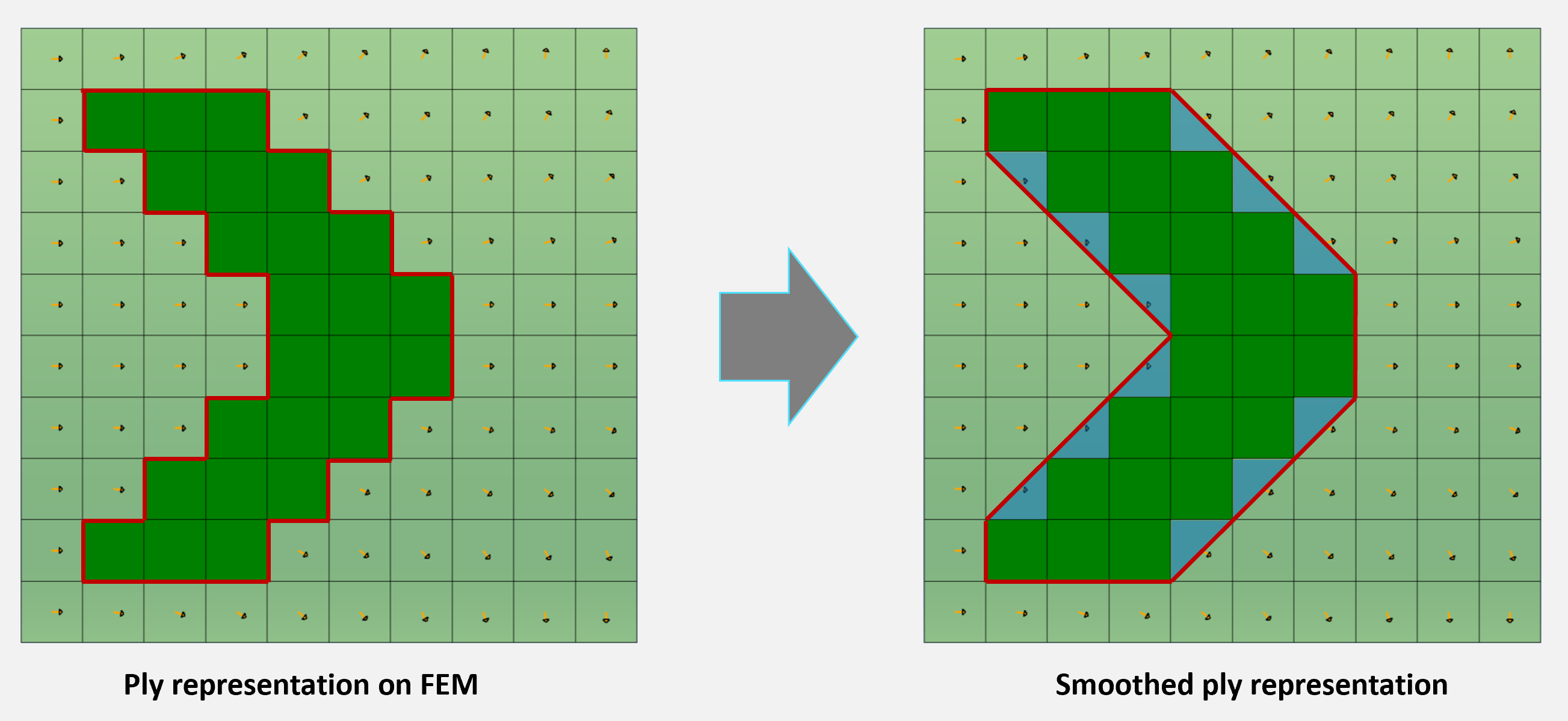
The second metric considered in the producibility score is the orientation of fiber angles relative to the ply boundaries. This metric is especially important for ATL or AFP layups to avoid zig-zag ply edges or “dog-ears” and “flags” at the corners of plies. Those issues can contribute to excessive thickness deviations through the laminate as well as weight growth. The second metric is based on the orientation of the fibers in each element relative to the smoothed ply boundary. Smoothing of the ply boundary for scoring is critical for a FEM-based ply because of the jagged edges that can be caused by element edges.



Ply Visualization
Review ply shapes, drops, and stacking sequence as well as cores and core taper in HyperX before exporting for manufacturing.
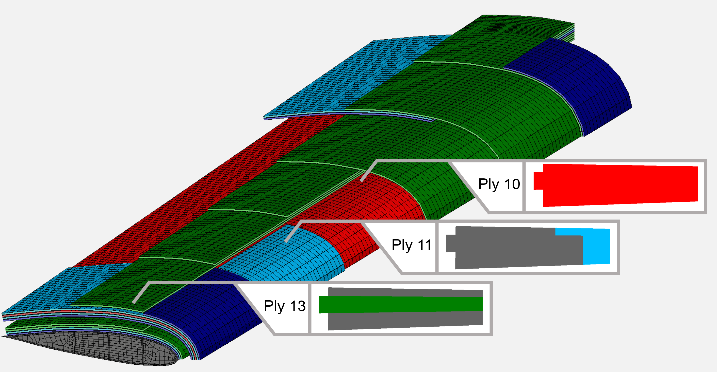
Once plies have been generated from optimization results, HyperX can overlay them on the FEM structure so that the user can assess manufacturability and determine if any modifications are needed. This view shows ply shapes, indicates where ply drops occur, and can also be used to visualize how the thickness and stacking sequence changes across a structure.
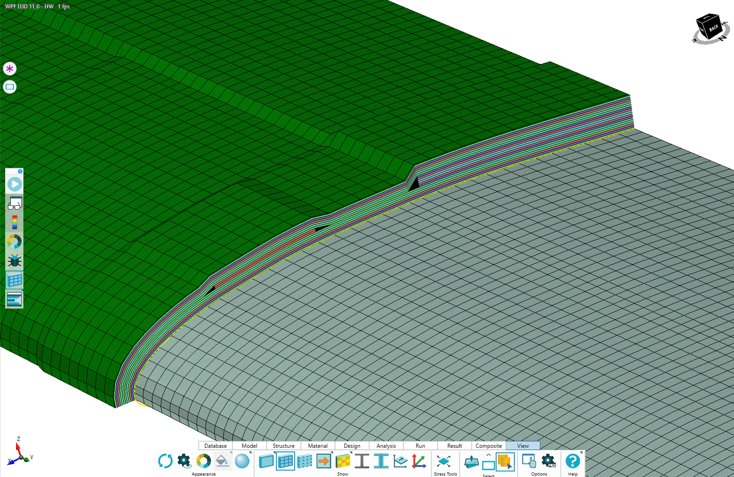

Two ply views are available: “exploded” and “topological.” The left view positions the plies with a uniform offset from the surface, which is useful to see which plies are in the same manufacturing sequence. The right view shows the plies in a draped visualization, as the part would be cured.


For sandwich panels, the honeycomb or foam core is also included in the visualization. Changes in core thickness are shown with taper between the two thicknesses.
Cut planes can be generated to slice through plies in a specific location and view stacking sequence or ply drops at an interior location on the structure.


Ply Modification
Users can manually modify plies after generation. HyperX provides several tools for easy editing. Updated margins can be generated after ply modification.
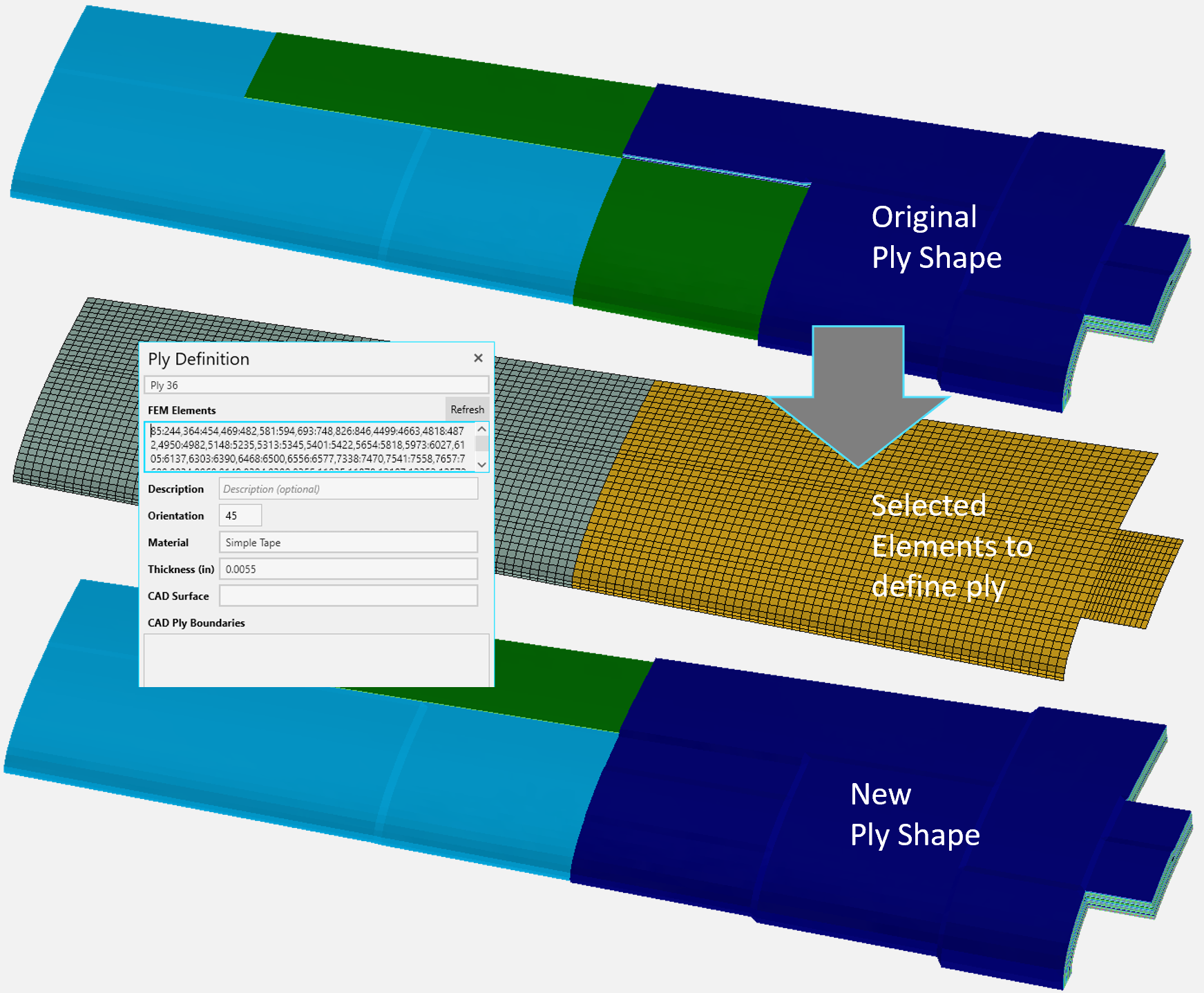

Ply shape is defined in HyperX by a list of elements that each ply covers. The powerful selection tools make it easy to change ply element membership. This includes: box selection, circle or ellipse selection, general polygon selection, and surface selection. Groups of elements within sets or zones can also be selected.
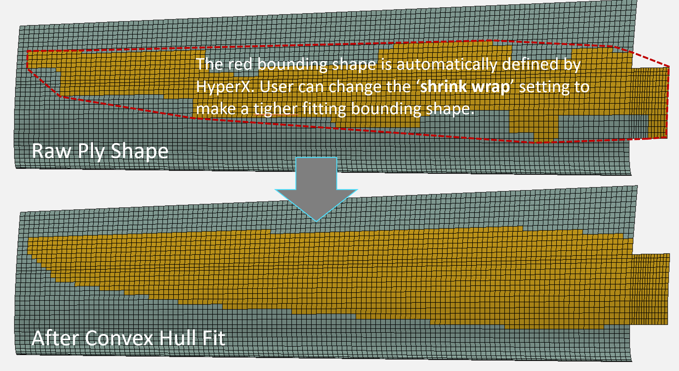
Advanced selection tools are also available to modify plies with custom shapes generated by HyperX. This includes: convex hull, bounding boxes, minimum bounding circle, minimum bounding ellipse.

Contact Us
This site is protected by reCAPTCHA and the Google Privacy Policy and Terms of Service apply.
