Panels and Beams
HyperX panel and beam designs replace FEM properties. They provide structural detail to the model in order to find optimal lightweight concepts, dimensions, materials, and laminates while achieving positive margins to aerospace analyses methods for all load cases.
Capability Pages

Introduction
The HyperX process for finding light weight designs is comprehensive. It is highly interactive and responsive, allowing you to narrow-down design decisions every step of the way. It starts with sizing optimization of many different panel and beam concepts.
For aircraft, using an Urban Air Mobility (UAM) eVTOL vehicle as an example:
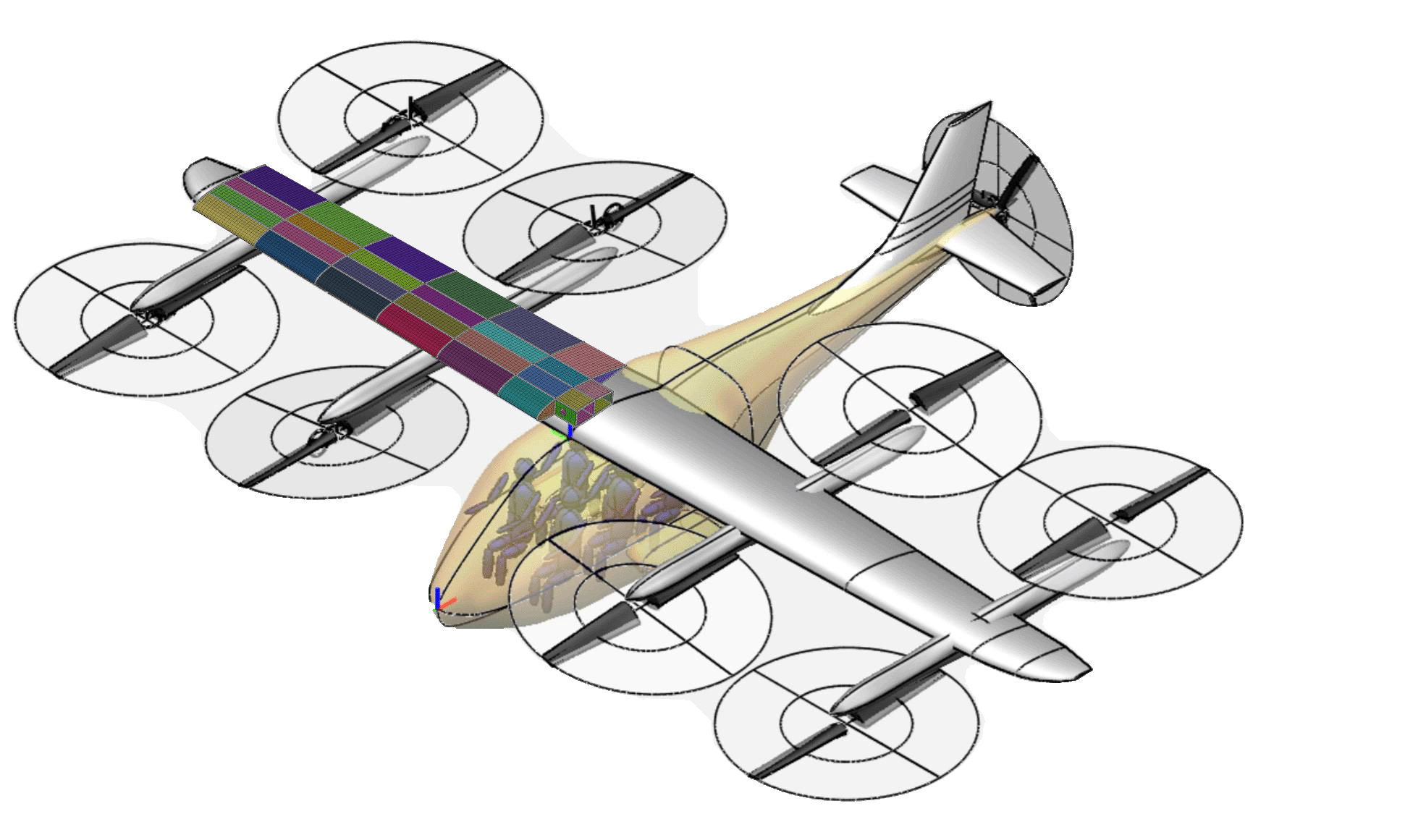

UAM wing.
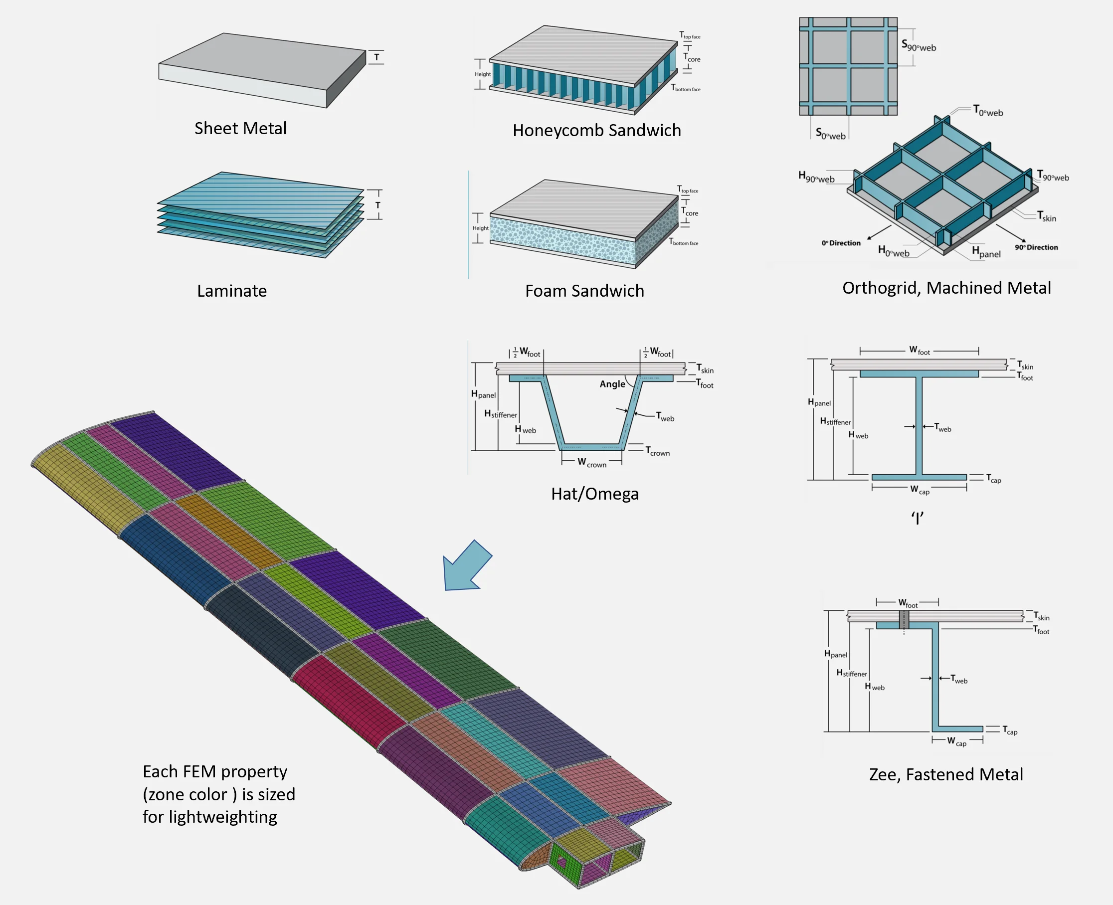

Different panel concepts evaluated for wing skin.
The design is in the early phase, before preliminary design review (PDR). The lightest panel concept is not yet known. There is a need to explore commonly used metal and composite constructions for the wing skin surface.
With HyperX, an engineer can trade between several different panel concepts to attain the lightest weight design. This is done by optimizing each concept’s unique dimensions to the loads in the corresponding skin zone, guaranteeing the lightest possible solution is returned.
For an additional level of optimization, panel concepts can differ between skin zones. For instance, the upper panels, which see a high amount of compression loading, may be lighter as a sandwich, whereas the more lightly-loaded nose may be more weight efficient as a solid laminate.
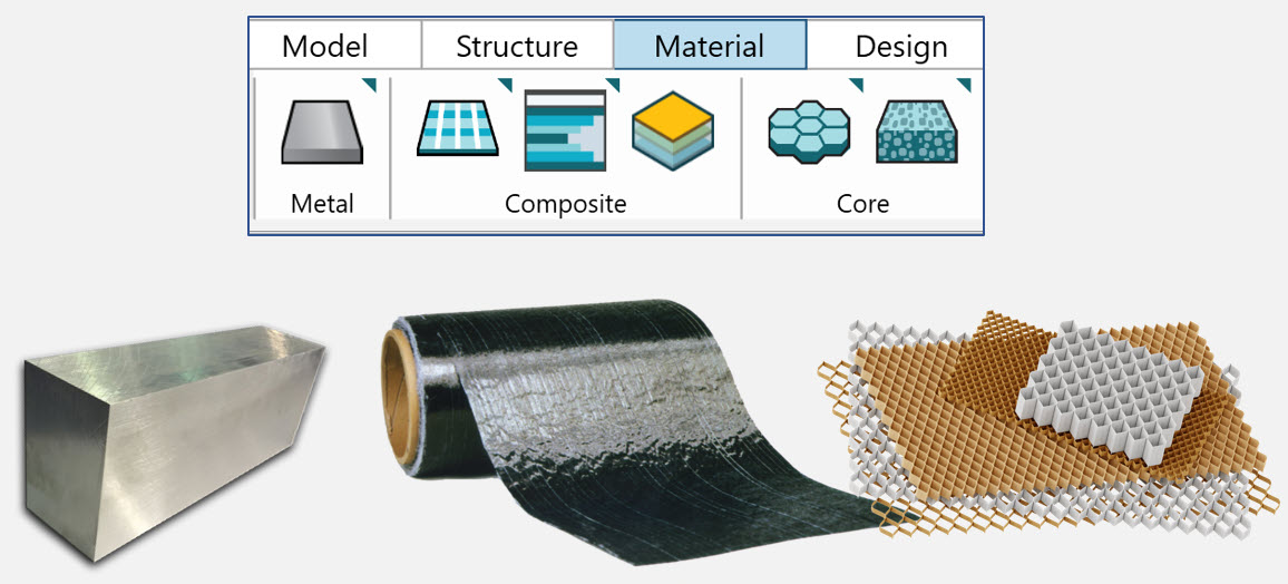
Concurrently throughout all of these concept considerations, different material systems can be explored as well.

Unstiffened Panels
The most basic panels are sheet metal and laminates. These concepts do not have stiffeners or cores to provide buckling stability.


Commonly used sheet metal and composite laminate unstiffened panels.
Unstiffened Panels are fundamentally driven by material strength and buckling stability failure analyses.
Unstiffened panel concepts can be applied to 2D shell elements.
Metal Plate
The simplest of all designs is metal plate. It has only two variables to optimize: thickness and material candidates. Plates can be thick or thin to represent sheet metal. Available stock sizes can also be used to define the sizing parameters within this design.


One Stack Laminate
Laminates have many variables to optimize: ply material, ply angle (such as 0˚, 45˚, 90˚), ply stacking order (such as 45/0/90 vs 90/45/0), and total laminate thickness.
HyperX has several ways to analyze and design laminates.
- Effective Laminates (EL) – in which only the laminate thickness and ply angle % are defined.
- Discrete Laminates (DL) – in which the candidate laminates are fully defined with a stacking order
- Laminate Families – a natively producible set of sequenced plies that make up discretely defined laminate candidates.
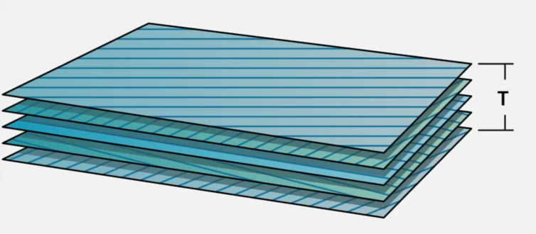

One Stack
Two Stack Laminate
Concept in which the two one stack laminates are each individually sized as part of a whole. Useful for honeycomb top and bottom facesheet transition ramp downs to a one stack laminate edge band.
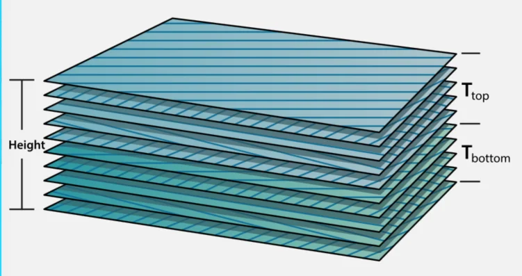

Two Stack
Three Stack Laminate
Similar to the two stack, but three one stack laminates are individually sized as part of the whole. Used much like the two stack, but the middle stack is laminate rather than core.
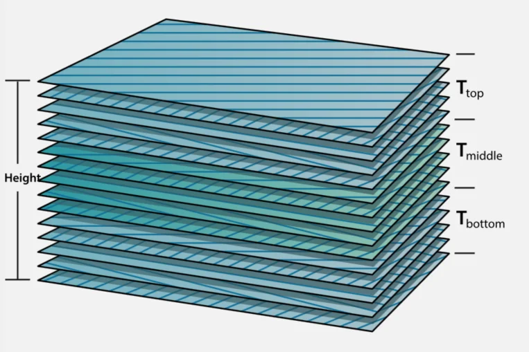

Three Stack
Sandwich Panels
Useful for structures that have biaxial compression and/or shear loading causing buckling. A commonly used aerospace composite panel concept, but not for primary loaded commercial airframes.


Commonly used honeycomb and foam sandwich panels.
Honeycomb and Foam
Sandwich panels are optimized by sizing each individual object – the top facesheet, the core, and the bottom facesheet – to its respective failure modes. Each object is prescribed dimensional bounds and material candidates.
In addition to material strength and buckling stability, HyperX provides unique sandwich analyses such as core shear strength failures caused by out of plane loading, flatwise tension with interlaminar shear, as well as wrinkling and intracellur dimpling for thin facesheets overlaid on large-cell core. Sandwich concepts can be applied directly to 2D shell elements.
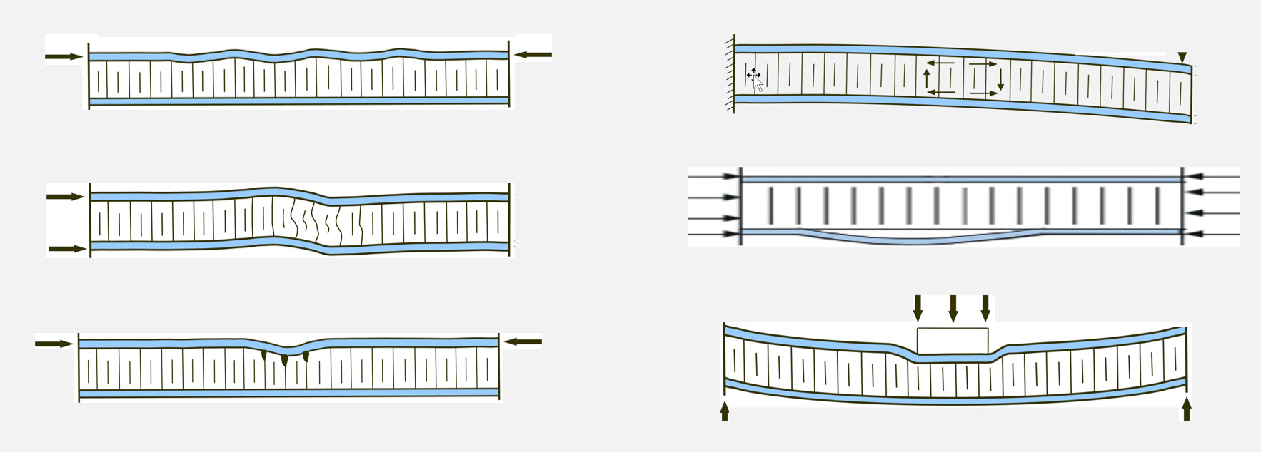

Stiffened Panels
Useful for structures that are mostly under uniaxial loading. Open sections such as ‘I” are often used for airframe wing skin and closed sections such as ‘Hat’ for fuselage skin.
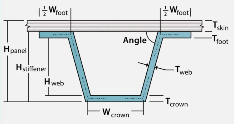


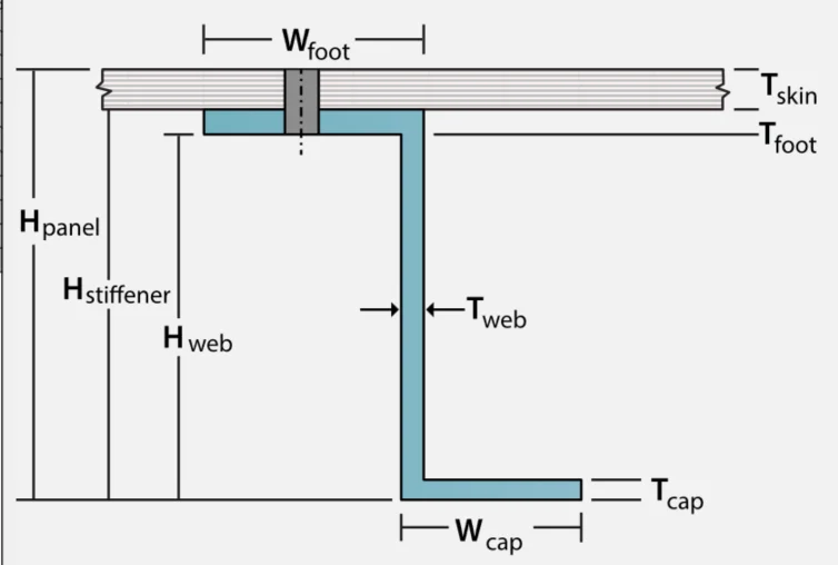


Commonly used composite hat and sheet metal fastened Zee stiffened panels.
Generally, wing skins are supported by relatively close rib spacing substructure, whereas the fuselage by closely spaced ringframes.
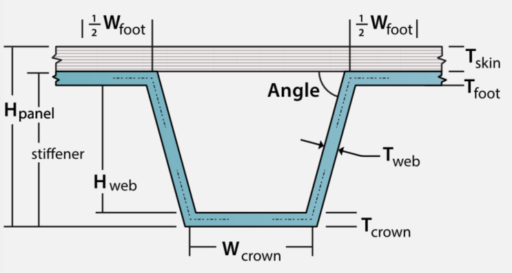
Each individual segment of a stiffened panel is represented as an object in the HyperX panel concept definition. Each object has its own unique sizing dimensions, material system candidates, and applicable failure modes. As an example, the skin thickness should be sized to account for local buckling between stiffener sections, whereas a stiffener web should be analyzed for its own local stability modes. The stiffened panel is also analyzed as an entire system, meaning additional failure analyses combine all objects together to evaluate modes such as buckling of the entire panel and crippling of the entire cross-section. Failure modes can also vary based on the type of stiffener applied to the panel. For example, open cross section panels must analyze lateral torsional buckling. But, closed cross-section concepts, such as hat/omega panels, the torsional rigidity stiffness of the enclosed cell is computed for buckling stability evaluation.


Flexural torsional buckling, curved or flat, simple or fixed boundary conditions, biaxial with shear including transverse shear flexibility.
HyperX supports several different strategies for modeling a stiffened panel. The simplest of which allows all objects to be ‘smeared’ into a single surface of 2D shell elements. This is accomplished by fully defining Aij, Bij, Dij stiffness terms for the shell elements. Refer to the technical papers for more information. This modeling strategy opens up all geometric design variables, particularly useful in early optimization trade studies.
As the design matures, various geometric variables (like stiffener spacing and height) are going to become set – thereby allowing individual objects be discretely modeled into the FEM with bar/beam/shell elements. All different modeling techniques are supported.
Bonded (Composite)
In addition to the sizing variables and failure analysis strategies outlined above, all bonded stiffener-to-panel concepts are optimized to account for the FAA requirement of a ¼” assumed crack in the bond line between the skin attached stiffener flange. This analysis is performed using the virtual crack closure (VCCT) energy method to quantify residual strength.


Hat/Omega

Two sheet
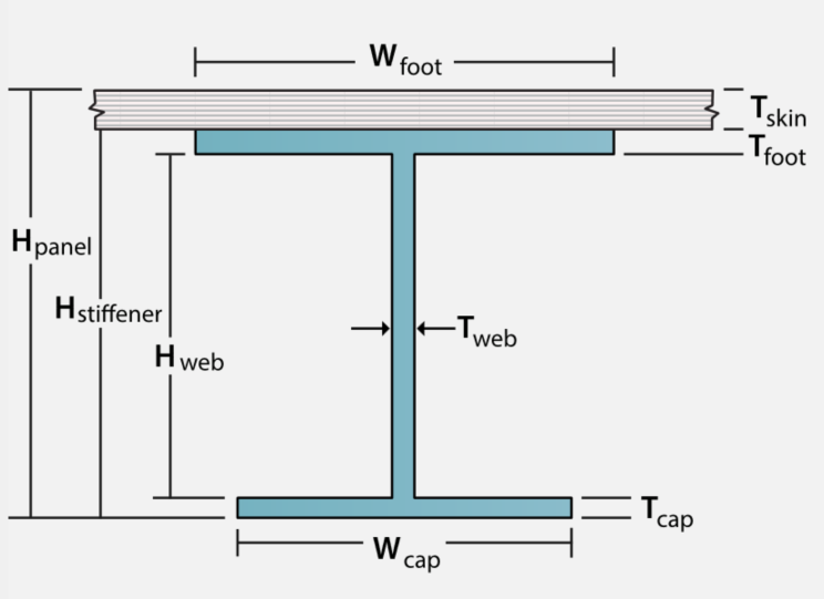

I
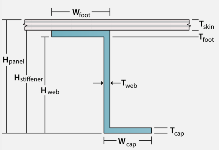

Zee
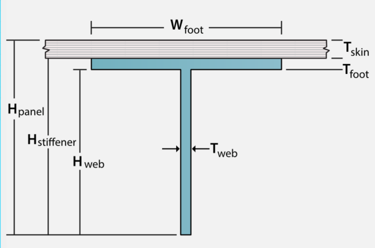

Tee
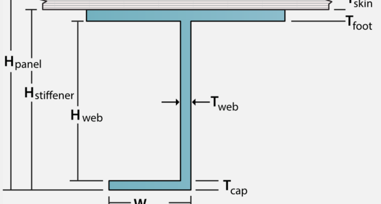

J
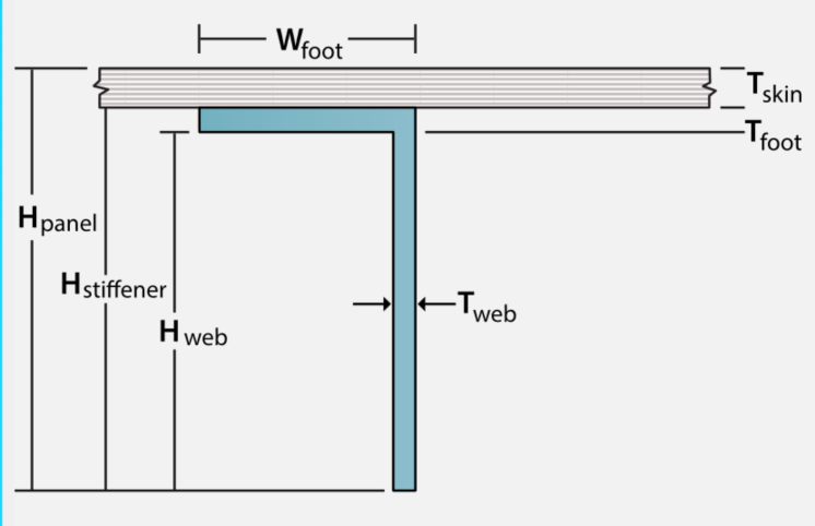

Angle
Fastened (Metal)
In addition to the bonded concepts above, HyperX stiffened-panel optimization can also account for stiffeners fastened to the skin. The thermoelastic Aij, Bij, Dij stiffness formulation for fastened panels is different than bonded panels due to the attached flange having its transverse strain being decoupled from the skin. There are also additional failure methods to analyze this case. If the stiffened panel is completely metal, traditional sheet metal NACA/NASA aerospace analyses are also performed.
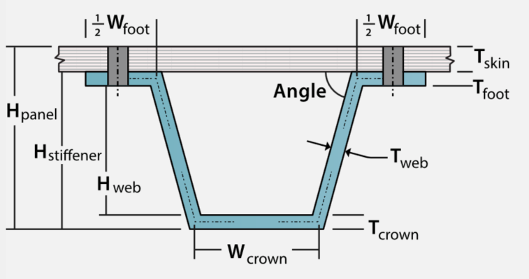

Hat Fastened
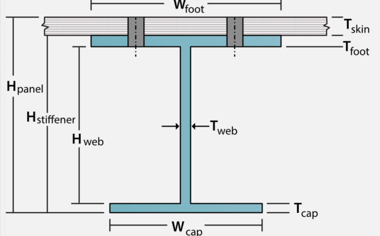

I Fastened


Zee Fastened
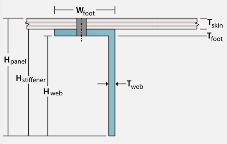

Angle Fastened
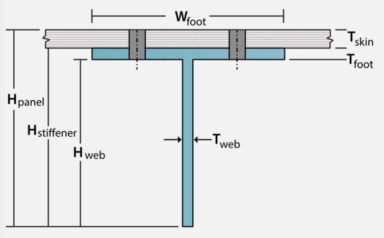

Tee Fastened
Grid Stiffened Panels
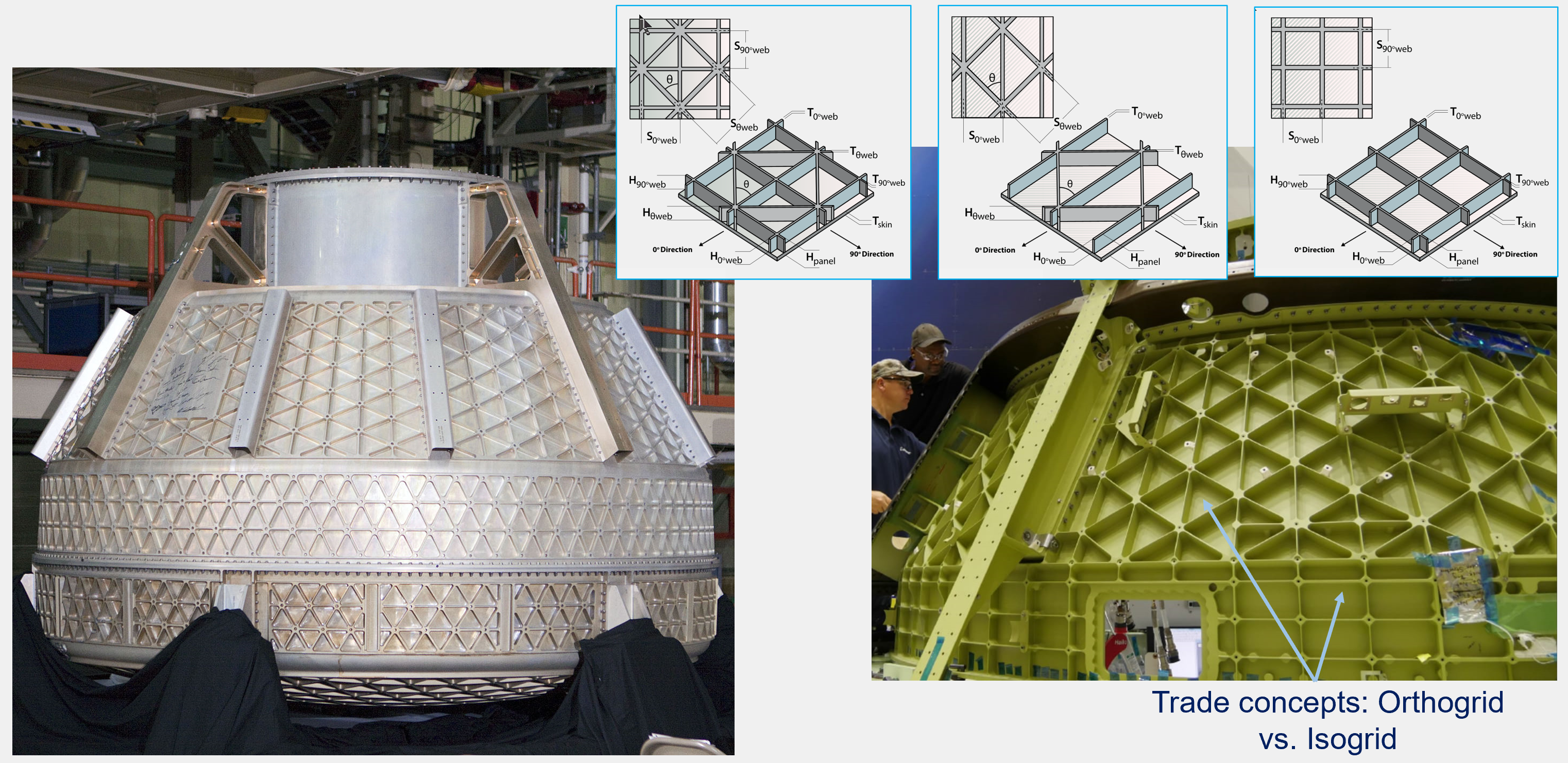

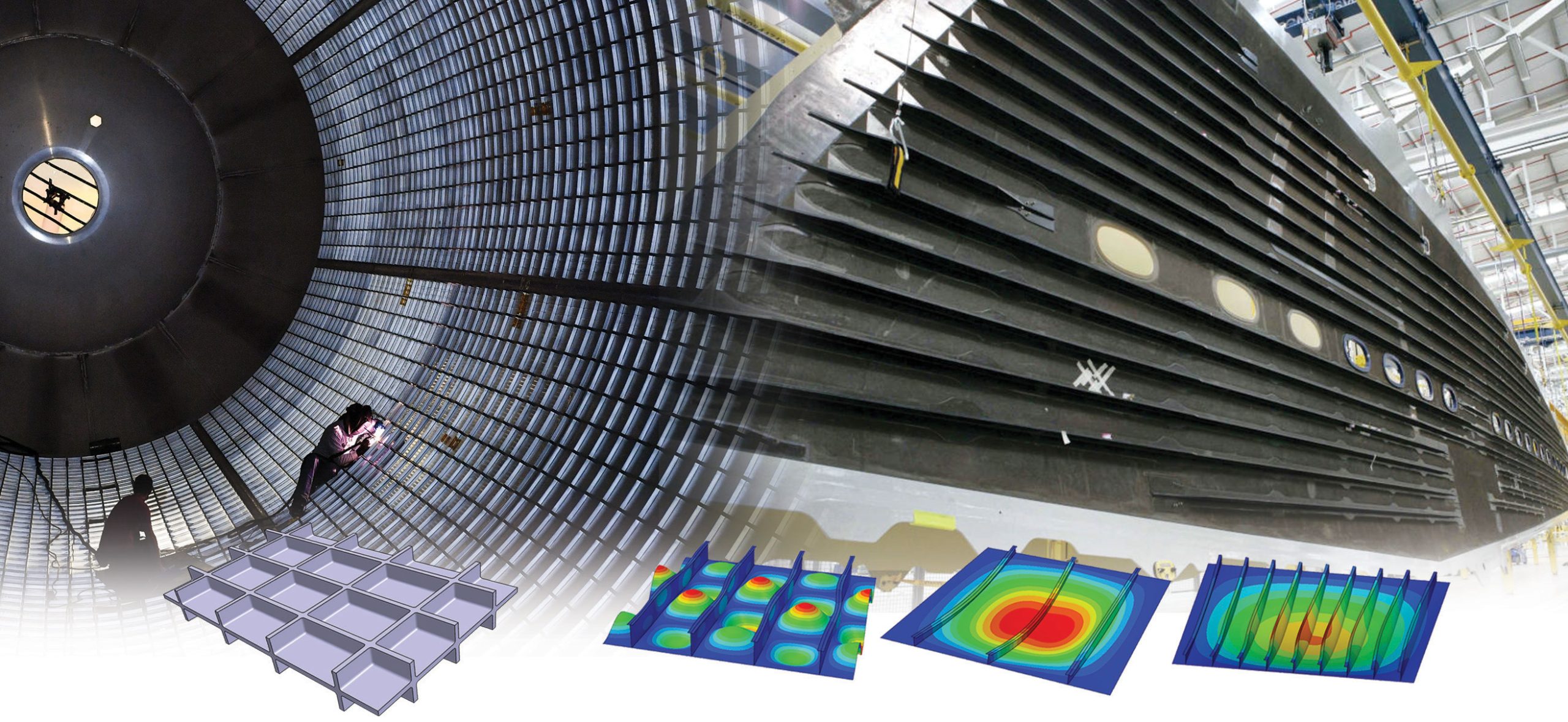
Commonly used machined metal grid orthogrid and isogrid stiffened panels. These concepts have many dimensions to optimize.
As with other HyperX stiffened-panel concepts, Each individual segment of the grid is represented as an object in the HyperX panel concept definition. Each object has its own unique sizing dimensions, material system candidates, and applicable failure modes.
HyperX supports several different strategies for modeling a grid-stiffened panel. The simplest of which allows all objects to be ‘smeared’ into a single surface of 2D shell elements. This is accomplished by fully defining Aij, Bij, Dij stiffness terms for the shell elements. Refer to technical paper for more information (https://collieraerospace.com/technical-papers/). This modeling strategy opens up all geometric design variables, particularly useful in early optimization trade studies.
As the design matures, various geometric variables (like stiffener spacing and height) are going to become set – thereby allowing individual objects be discretely modeled into the FEM with bar/beam/shell elements. All different modeling techniques are supported.
Orthogonal
The Orthogrid is the most commonly used grid stiffened panel concept. Applications include buckling critical, low to medium pressurized fuel tanks of rockets. These concepts are machined out from stock plate. Bumped forming is used to produce cylindrical curvature.
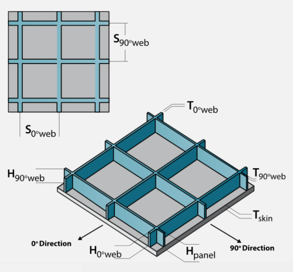

Orthogrid
Angular
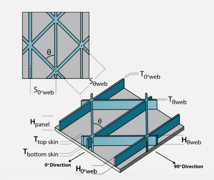

Isogrid
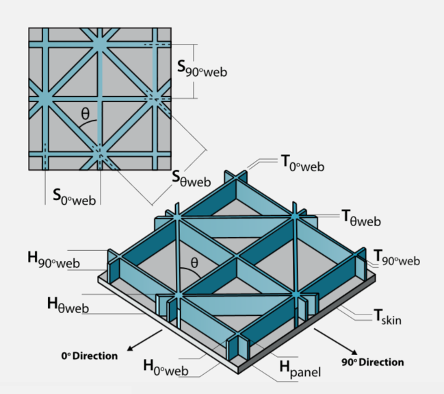

Generalgrid
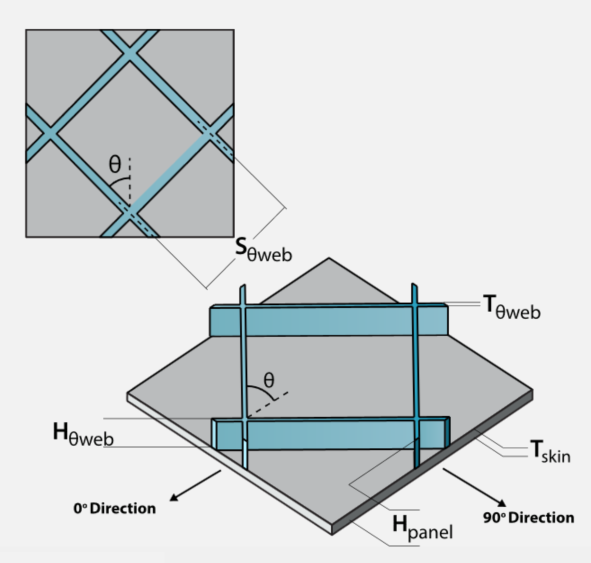

Wafflegrid
Beams
Beams can be analyzed and sized. Specific beam stiffness formulation and failure analyses are performed. Modeled with 1D elements.


Commonly used I, C channel, and circular tube beams.
1D elements allow for the analysis and sizing of each individual object within the beam. Much like stiffened-panel concepts, each object has its own sizing dimensions, material candidates, and applicable failure modes. The beam is also evaluated as a whole, particularly for stability criteria.
Open Cross Section
Most common for civil construction is the I beam.
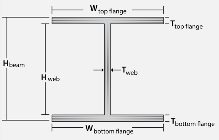

I beam
Simple cap is the most commonly used beam for aerospace wings. It is used for spar caps and rib caps. It is supported from buckling by its attaching skin and rib.
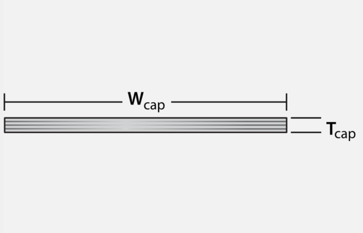

Cap beam
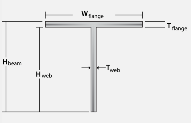

Tee beam
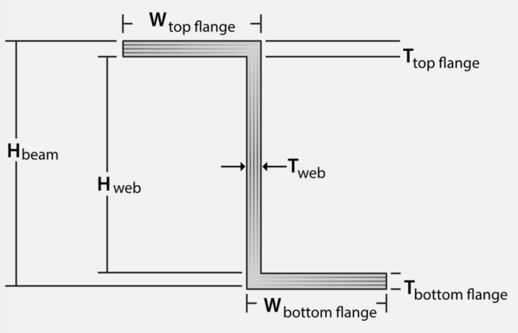

Zee beam
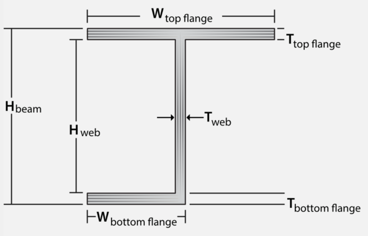

J beam
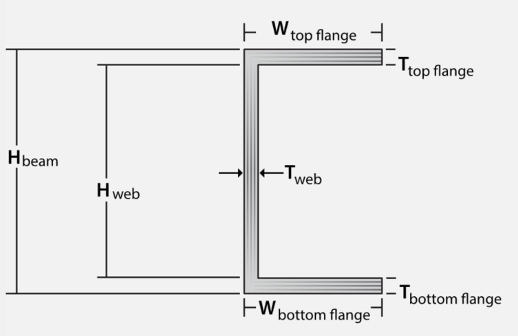

C channel beam
Closed Cross Section
The closed cross sections are often used for unsupported span lengths – not attached to other structure. Typical applications include lunar landing legs, landing gear, and engine thrust supports.
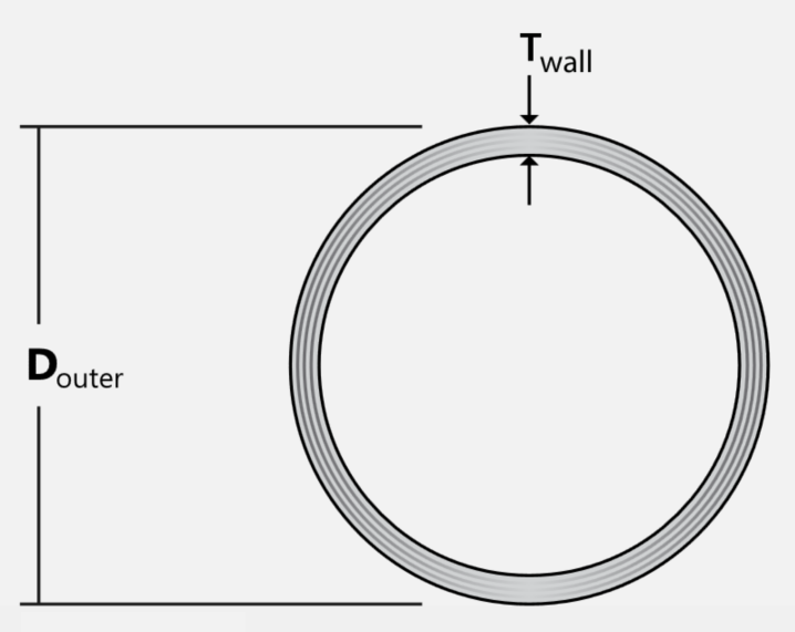

Circular tube beam
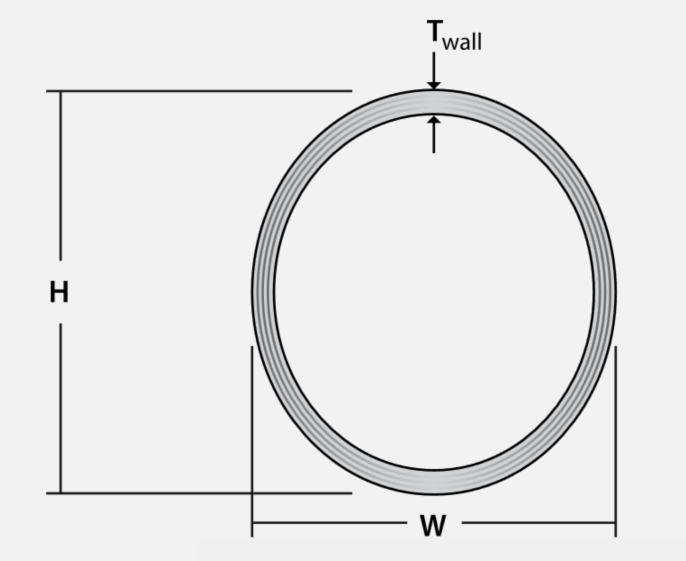

Elliptical tube beam
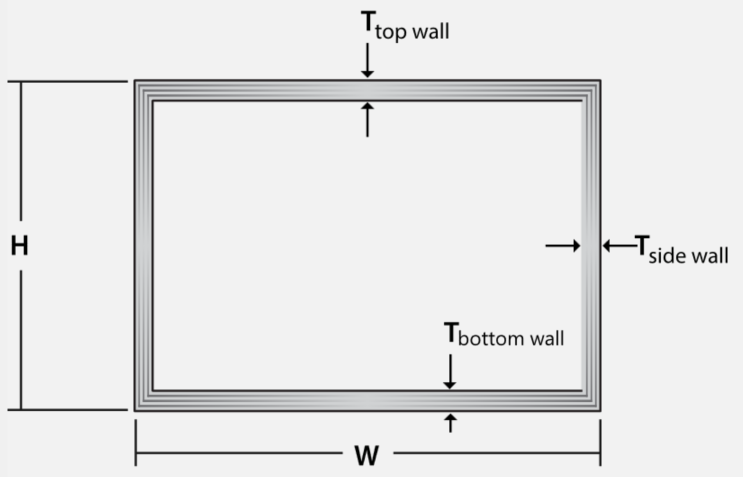

Box tube beam
Contact Us
This site is protected by reCAPTCHA and the Google Privacy Policy and Terms of Service apply.
