HyperXpert: Design Insights

HyperXpert expands the traditional HyperX workflow. It provides access to ALL possible (i.e. positive margin) design options in the design space, and a way to compare those designs with respect to both weight and producibility concurrently, rather than one followed by the other.

Using a full factorial DOE-type approach, this tool systematically varies all cross-sectional variables across a part and organizes the data in terms of both weight and producibility. This allows engineers to quickly compare results, understand trends, and decide the “best” design for themselves.

The Stratolaunch aircraft next to hangar, the world's largest aircraft.

Design for Producibility

Integrate subjective manufacturability considerations in to the earliest conceptual design phases

The Stratolaunch aircraft next to hangar, the world's largest aircraft.

Safety in Data

Feel confident in your design choices, knowing you did your due-diligence to understand the entire design space

The Stratolaunch aircraft next to hangar, the world's largest aircraft.

Instantaneous What Ifs

Quickly understand the benefits and consequences of each decision – with the same speed and interactivity HyperX has always provided

1. Generate data points

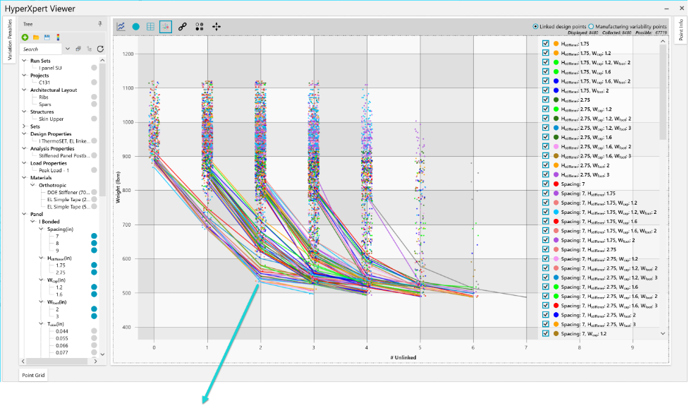
Each data point represents a unique part design. Innate to HyperX is its ability to efficiently generate 1000’s of designs, that pass all analysis margin checks for all load cases. In this example there are over 8000 unique part designs available for you to choose from.  The HyperXpert Viewer displays this data and provides you instantaneous filtering and pairing of selected variables. Pareto frontier curves are plotted to identify the best performant design points per filtered value.


2. Inspect data points

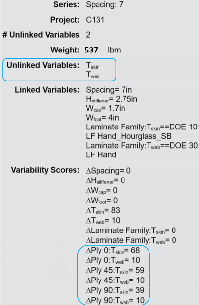
Hovering the mouse over any data point results in this pop-up dialogue, which reports which variables are consistent across the part along with their values.  This particular point represents the lightest design that has two unlinked variables: the laminates of the skin and stiffener web, and resulting Δ change in ply counts across the part’s zones.


3. Select a data point, visualize the design

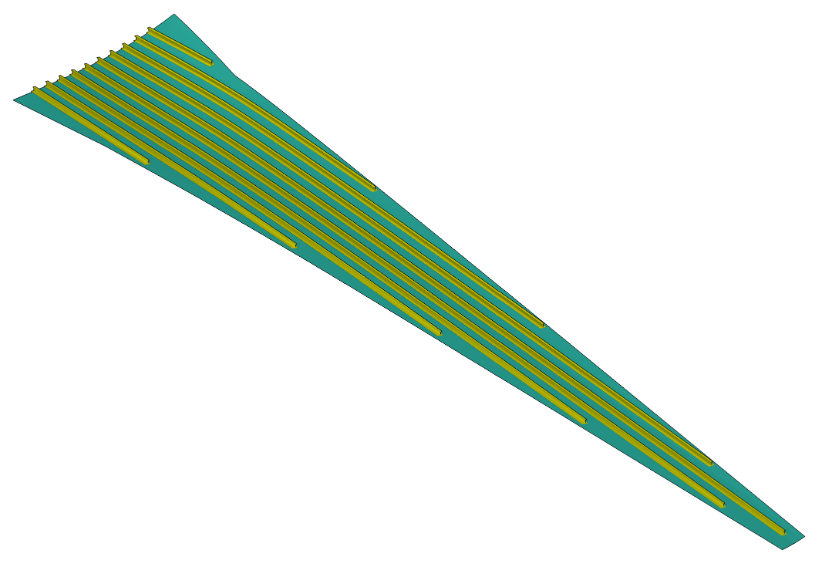
By selecting this point the stiffener dimensions are linked, but you can continue to optimize the design with the remaining unlinked sizing variables – in this case the skin and stiffener laminates. After the sizing, you can choose to have HyperX generate CAD stiffeners for visual confirmation, as in this example of a commercial wing skin. 

Challenge

To understand HyperXpert is to understand two fundamental topics: (1) the idea of design variance across a part surface as a measure of producibility, and (2) quantifying the producibility variance impact on weight.

This simple example will illustrate the importance of both.

Take the UAM wing shown below. For simplicity’s sake, let’s say you’d like to size the upper skin as a metal plate. All possible thicknesses are given to define the design space.

Running a preliminary sizing on the entire upper skin, HyperX will find the thinnest plate that satisfies all strength and stability criteria. This is the most producible design, since there is no variation across the skin surface. Let’s call this Design #1.

The figure below illustrates the individual panels of the upper skin formed by the rib-and-spar-substructure and the corresponding Nx load gradient for one of the critical load cases.

It is typical aerospace practice to allow particular design variables – in this case, thickness – of each panel to vary across the part surface. In this instance, HyperX will find the thinnest plate that will survive the load for each panel, rather than assigning the controlling thickness to the entire surface. This is the lightest weight design, but comes with increased variation in design across the skin surface (and therefore a decreased level of producibility by comparison to Design #1). We’ll refer to this as Design #2.

For each design, which are both considered viable options for this upper skin part, a variation score (based on the amount of change in design variables across the part surface) and corresponding weight are calculated.

By plotting weight vs producibility, these values can be visually compared to one another.

The two designs tracked so far represent the bookends of this problem. Based on the number of candidates in the given design space and the number of panels in the wing skin part, there are potentially 1000s more skin part designs.

By running a full factorial design of experiments (DOE) we can systematically identify all viable wing skin designs, calculate their corresponding weight and variation, and plot them accordingly.

This plot provides engineers a way to compare designs, understand trends, and ultimately select the design that best meets their needs.

For this simple example, it may seem possible to programmatically tune the input variables, run HyperX, extract the results, assign each result a weight and variability score, and plot the results externally. And that’s true. But, you could imagine this process would get increasingly tedious, time consuming, and computationally intensive as the number of design variables increased. For example, what if you wanted to implement T-stiffeners down the length of the wing. Now, not only can each panel vary in thickness, but it can also vary in stiffener spacing, width, thickness, and so on.

HyperXpert extends the HyperX workflow – which produces a single solution from a single input design space – by giving users access to the Engineers gain insights on their designs, increased confidence their design decisions, and comfort in the magnitude of data they consumed; all while keeping both weight and producibility in mind.

Solution

HyperXpert is in general a design of experiments (DOE) tool. Given a part surface and a defined design space (i.e. options for material systems, stiffener cross sections), as well as a given set of failure criteria that a part needs to satisfy, this tool runs a full factorial DOE. In HyperX-terms, it uses the same HyperX solver to optimize designs to user selected failure criteria. For each of these workable solutions, a weight and relative producibility score (in terms of variance in design across the part surface) are calculated.

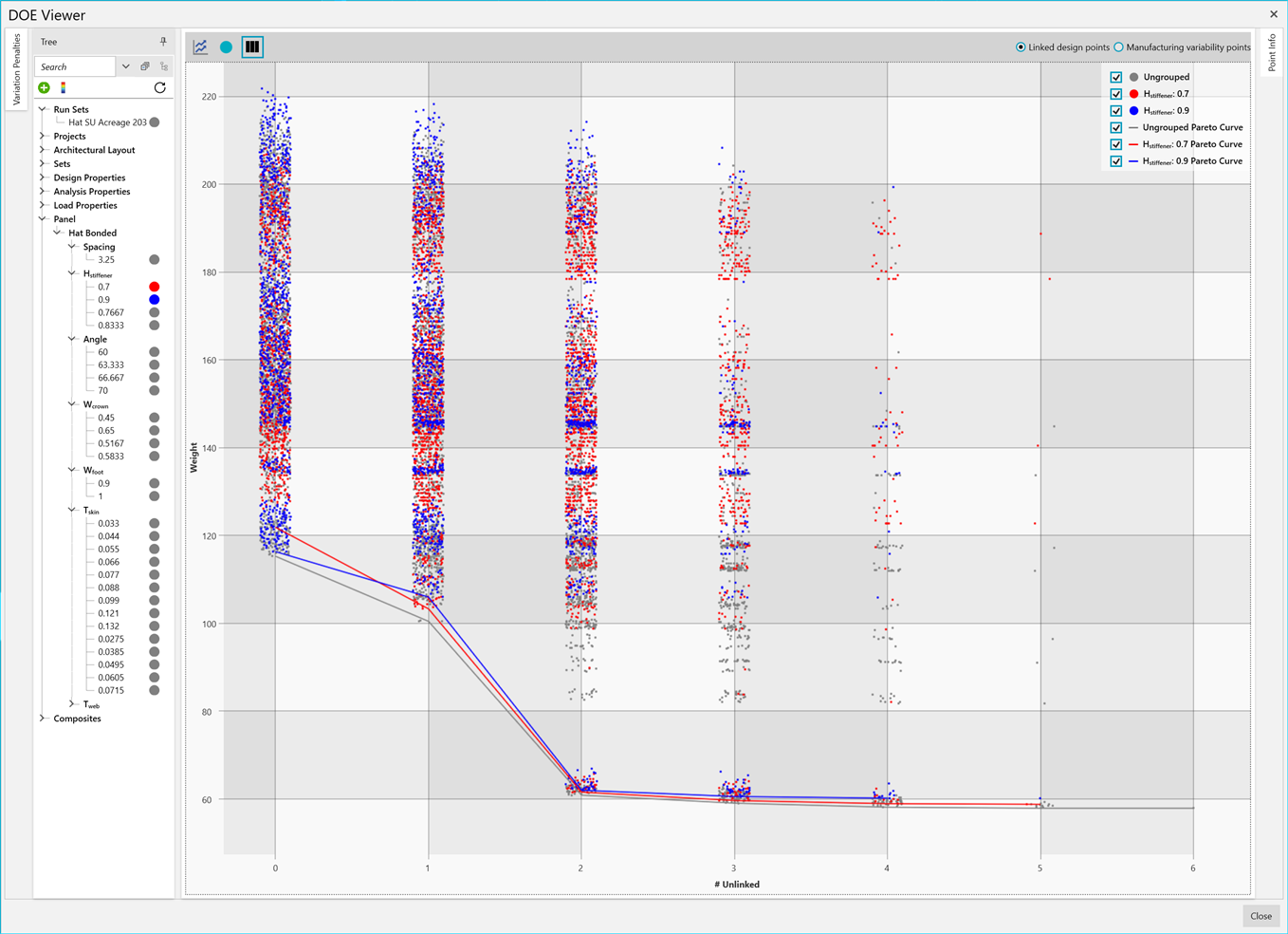
From here, the HyperXpert interface instantaneously displays the best viable options in the design space in a weight vs. variation plot. This plotting interface offers trendline creation, filtering, pareto frontiers, etc.; all of which serve to allow the engineer to glean meaningful design insights and use their own data-driven subjectivity to determine their “best” part design.

This powerful HyperXpert plotting interface is shown in the example above. Here, variation is quantified in terms of “unlinked variables.” A linked variable is a type and value that spans the surface of a part. For example, a cross-sectional dimensionsuch as stiffener height =1.2” that spans the length of the part. The more cross-sectional dimensions are linked across a part, the easier that part is to manufacture.

By plotting weight as a function of unlinked variables for the trillions of workable designs in the space, we can quickly understand that, for example, that while there is significant gain in producibility in going from 5 unlinked variables to 2 (i.e. ensuring that 3 dimensions are These data driven insights provide you with valuable insights into design decisions such as stiffener tooling mandrels.

Additional Resources:

DOE Explore

Problem: your engineering team is designing an aircraft structure using industry standard CAD and FEA products, but you have no way to perform automated structural sizing nor margin writing to classical aerospace analysis methods. Because of this your aircraft structure might be 1) over weight, 2) behind schedule, 3) hard to manufacture, with 4) uncertain certification progress and reporting.

Need:  a commercial product that automates your company’s design and analysis process and that digitally connects data to your existing software packages. To be used from concept through preliminary design, all the way to final design and part drawing release.

Solution: use HyperX with your FEA and CAD tools to achieve a fully-optimized, manufacturable practical design. Eliminate costly hours of manual calculations and spreadsheets, by using HyperX by the entire engineering team.

Standardize your company’s analyses with verified methods out of the box, or plug in your company’s own proprietary analysis methods. Since the same analysis methods are used from preliminary to final design, there are no surprise negative margins of safety that would detrimentally affect your schedule or cause weight growth.

  • Decrease weight by optimizing each panel, beam, and joint; ensuring a lightweight design
  • Shortened schedule by reducing design cycle time and engineering labor hours
  • Increase producibility by enforcing design rules and sizing to your company’s metal and composite construction fabrication processes
  • Certify structures faster by analyzing hundreds of aerospace industry standard failure methods, generating real time stress documentation
HyperX Logo Center Your Design.

Aerospace Structural Analysis and Design Optimization

© 1995 – 2023 Collier Aerospace Corporation. All Rights Reserved.

Software

What is HyperX

Why Use HyperX

When to Use HyperX

Where is HyperX Used

Videos

Capabilities

Support

Contact Us

Training

Latest Version

Technical Papers